
Caravan AWD V6-201 3.3L (1991)
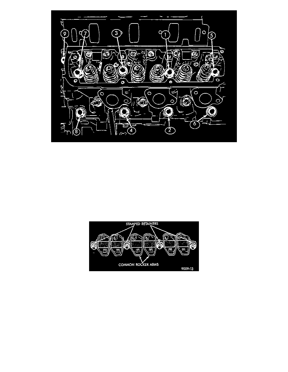
Fig. 31 Cylinder Head Tightening Sequence
5. Tighten the cylinder head bolts 1 through 8 in the sequence shown in Fig. 31. Using the 4 step torque turn method, tighten according to the
following values:
^
First-All to 61 Nm (45 ft. lbs.)
^
Second-All to 88 Nm (65 ft. lbs.)
^
Third-All (again) to 88 Nm (65 ft. lbs.)
^
Fourth + 1/4 turn Do not use a torque wrench for this step
NOTE: Bolt torque after 1/4 turn should be over 122 Nm (90 ft.lbs.). If not, replace the bolt.
6. Tighten head bolt number 9 Fig. 31 to 33 Nm (25 ft.lbs.) after head bolts 1 thorough 8 have been tighten to specifications.
7. Inspect push rods and replace worn or bent rods.
Fig. 32 Rocker Arm Shaft Retainers
8. Install push rods, rocker arm and shaft assemblies with the stamped steel retainers in the four positions, tighten to 28 Nm (250 in.lbs.) Fig. 32.
CAUTION: The rocker arm shaft should be torqued down slowly, starting with the center bolts.
9. Place new cylinder head cover gaskets in position and install cylinder head covers. Tighten to 12 Nm (105 in.lbs.).
INTAKE MANIFOLD SEALING
The intake manifold gasket is a one-piece stamped steel gasket with a sealer applied from the manufacturer. This gasket has end seals incorporated
with it.
WARNING: Intake manifold gasket is made of very thin metal and may cause personal injury. Handle with care.
1. Clean all surfaces of cylinder block and cylinder heads.