
Caravan AWD V6-201 3.3L (1991)
Battery/Ambient Temperature Sensor (CCD Broadcast)
The battery temperature sensor is located in the Powertrain Control Module (PCM). This CCD broadcast information is used to control charging system,
engine and transaxle operation. The TCM uses the battery temperature signal to estimate transaxle fluid temperature. When the TCM detects lower
temperatures, it adjusts the operation of the transaxle to allow for slower response of the valves and fluid. If a failure of the Transmission Temperature
Sensor occurs, the TCM uses the Battery Temperature signal along with engine coolant temperature to calculate the temperature.
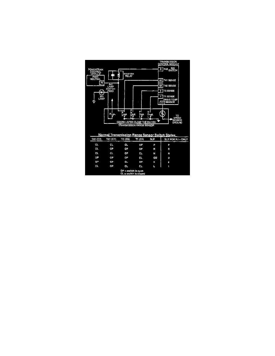
Shift Lever Position (SLP)
The TCM identifies the position of the manual lever by comparing the current switch positions of the Transmission Range Sensor (TRS). This is
accomplished by logic circuitry within the TCM. The primary function of SLP logic is to provide safe, continuous, but limited operation of the transaxle
with the presence of an invalid or transition input code. The SLP logic function screens the input codes from the switches and provides an SLP output
signal to control actual gear selection.
Inputs include the codes indicated by the TRS current shift lever position, pressure switch indications and speed ratio data from the input to most of the
other functions in the TCM.
The identified position is stored in memory. The current switch position is determined by sensing the voltage changes that occur at the corresponding
TCM pin terminals for the switches. The TCM receives the switch signal and processes the data. On vehicles with a BCM, the TCM sends the Shift
Lever Position information to the BCM and the cluster electronic PRNDL display via the CCD Bus. The cluster electronic PRNDL display
illuminates the appropriate shifter position indicator on the instrument cluster. For vehicles without a BCM, the shifter position indicator is
cable-operated.
CAUTION: An incorrect input (for example, a defective switch) of one of these positions could, with sufficient time, result in either a pressure switch
or speed check fault, when in fact the real cause is a TRS fault. this type of fault can occur, for example, when the manual valve porting is in reverse but
the code is indicating "OD." In this case, the low/reverse pressure switch data and input speed data will not agree with the expected results for shift lever
position = "OD." Therefore, it is important to perform a shift lever position test with the DRB scan tool before diagnosing any trouble codes.
It is extremely important that accurate shift lever position data be available to the TCM. The accuracy of any diagnostic trouble code found in memory is
doubtful unless the Shift Lever Test, performed on the DRB Scan Tool, passes without fail.
Torque Management Signal (CCD Broadcast)
With some engines, the TCM sends a direct input, torque management request signal to: the PCM. This occurs during high torque, high speed 1-2, 2-3,
4-2 and 3-1 shifts. The TCM torque management request signal is used in order to reduce the torque applied in the 2-4 and OD clutches. The PCM uses
the TCM's torque management signal to shut off a certain number of fuel injectors and to retard ignition timing slightly. This controls or reduces torque
output of the engine during certain shift sequences. The torque reduction is not detectable by the driver and lasts for a very short time period. The PCM
sends a confirmation of the request to the TCM over the CCD Bus. If the confirmation signal is not received by the TCM, a diagnostic trouble code will
eventually be set.
The torque management signal is basically a 9-volt supply to the PCM. A torque management request is recognized by the PCM when the TCM grounds
the circuit. The circuit at the TCM is called TRD link, which stands for "Torque Reduction Link."