
Caravan AWD V6-201 3.3L (1991)
Wiper Switch: Testing and Inspection
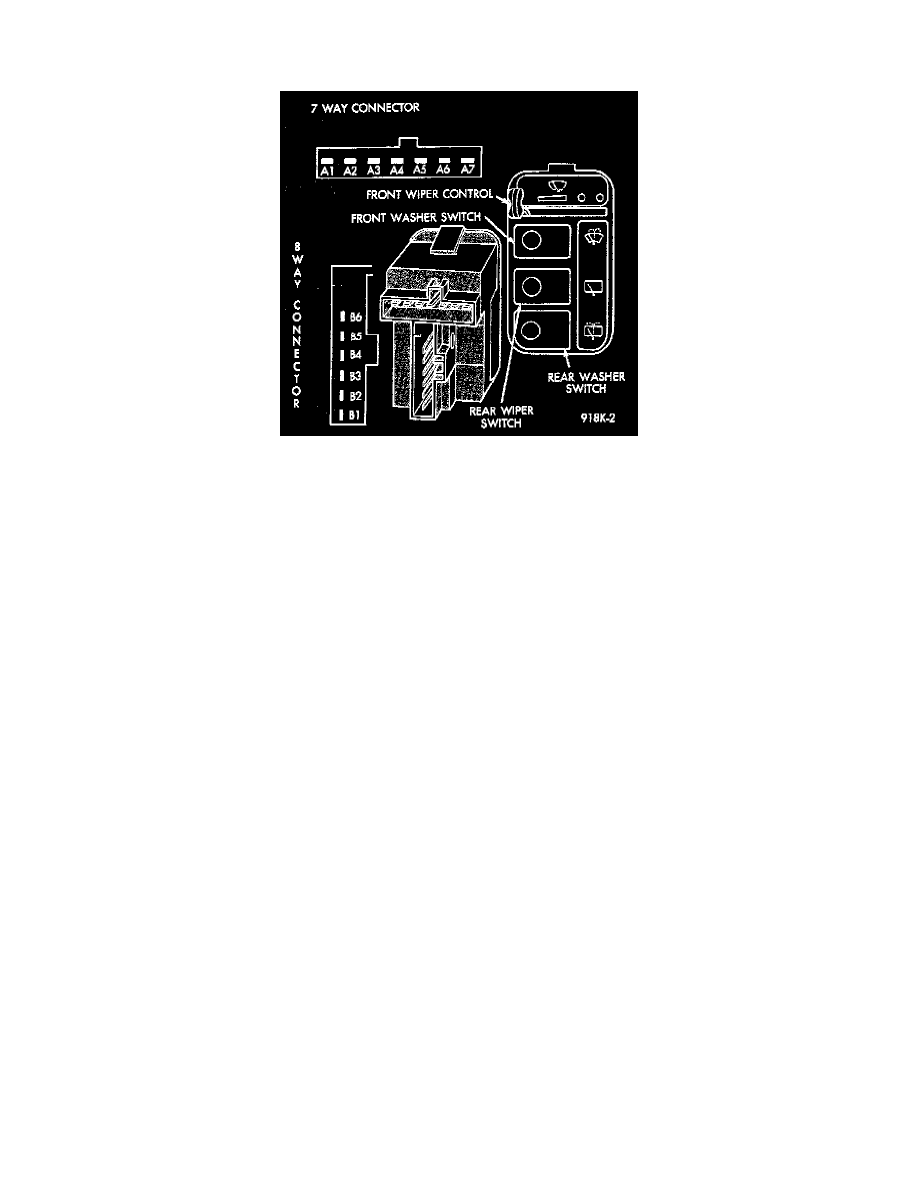
Combination Front And Rear Wiper/Washer Control Pod Switch Operation And Testing
Wiper POD Switch
The front wiper control portion of this assembly is a horizontal, sliding action with five clearly defined detent positions OFF, MAX, DELAY, MIN
DELAY, LO and HI as shown in the diagram. These provide the following functions.
1. OFF position.
-
The left most detent of the switch.
-
Turns OFF the front wiper and allows the front wiper blades to return to their PARK position.
-
There shall be continuity between terminals A6 and A4.
-
If not replace POD switch.
2. Intermittent MAX DELAY position.
-
Position at the left end of a variable resistor and provides the maximum delay signal level to the body controller, which directly operates the
front wipers in the delay mode.
-
There shall be continuity between terminals A7 and A5, A3 and B3.
-
There shall be a resistive valve of 210,000 to 390,000 ohms between terminals A1 and B3.
-
If not replace POD switch.
3. Intermittent MIN DELAY position.
-
Position at the right end of the variable resistor and provides the minimum delay interval signal level to the body controller.
-
There shall be continuity between terminals A7 and A5, A3 and B3.
-
There shall be a resistive valve of 350 to 650 ohms between A1 and B3.
-
When the slide is moved from MAX DELAY to MIN DELAY and vice versa:
Continuity between terminals A7 and A5, A3 and B3 shall be maintained.
The resistive valve between terminals A1 and B3 will decrease as the control is moved from max delay to min delay or increase when
moved from min delay to max delay.
-
If not replace the POD switch.
4. Continuous LOW (LO) position.
-
Position which turns ON the front wiper motor in the continuous LOW speed mode.
-
There shall be continuity between terminals A4 and B3.
-
If not replace POD switch.
5. Continuous HIGH (HI) position.
-
Position which turns ON the front wiper motor in the continuous HIGH speed mode.
-
There shall be continuity between terminals A4 and B3.
-
If not replace POD switch.
6. The front washer switch portion of this assembly is a push ON, momentary action and provides:
-
Power to the washer motor when the front washer button is depressed.
-
Power to the body controller to turn the front wiper system ON when the front washer button is depressed.
-
There shall be continuity between terminals B4 and B3 when the front washer button is depressed.
-
If not replace POD switch.
7. The Rear Wiper switch portion of this assembly is a push ON, push OFF latching action and provides:
-
A ground signal to the rear wash/wipe module to turn the rear wiper system ON when rear wiper button is latched down.
-
There shall be continuity between terminals B5 and B2 when the rear wiper button is depressed and latched down.
-
When the rear wiper button is latched, the ON indicator lamp will light only when headlamps are on.