
Charger SRT-8 V8-6.1L (2009)
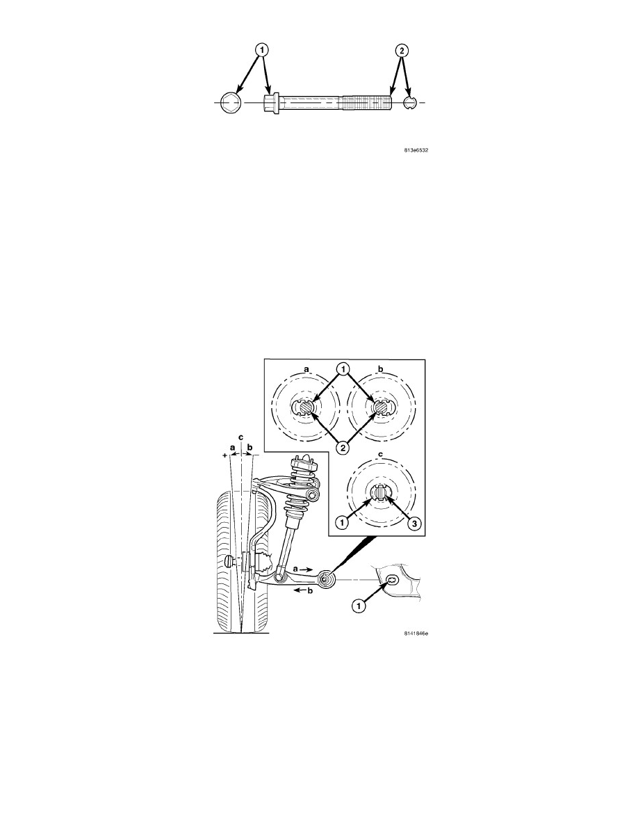
CAUTION: Wheel alignment adjustment bolts have offset grooves cut into the length of the bolt (2). If removing or installing lower control
arm or tension strut mounting bolts that have these grooves, DO NOT ROTATE THE BOLT. To remove the bolt, hold the bolt
head stationary and rotate the nut, then slide the bolt straight out of the bushing. This is necessary to avoid damaging the bat
wings in the bushing inner metal or cradle.
4. Hold the head of the control arm or tension strut mounting bolt stationary and remove the nut. Slide the bolt straight out of the bushing and
discard.
CAUTION: When installing an adjustment bolt, be sure to install it in the correct direction. Lower control arm rear mounting bolts must be
installed from the rear-forward and lower control arm front mounting bolts must be installed from the front-rearward.
NOTE: The grooves on the adjustment bolts are off-center forcing the bolt to be installed in one of two ways depending on whether more
positive or negative camber or caster is necessary. The Bolts must be rotated 180° to achieve either more positive or negative camber
or caster. DO NOT force the adjustment bolt.
NOTE: The original (non-grooved) mounting bolt (3) lies through the center of the hole (1), between the "bat wings" as shown in (c).
5. Camber Adjustment - The adjustment bolts are designed to work in conjunction with "bat wing" holes that are formed into the engine cradle (1)
allowing for lower control arm movement approximately 0.3° in either direction.
-
To achieve more positive camber, refer to (a) in the figure. Move the control arm in the desired direction, then insert the adjustment bolt (2)
with a washer installed through the bat wing hole in the engine cradle (1) and round hole in the bushing inner metal.
-
To achieve more negative camber, refer to (b) in the figure. Move the control arm in the desired direction, then insert the adjustment bolt (2)
with a washer installed through the bat wing hole in the engine cradle (1) and round hole in the bushing inner metal.