
Charger SRT-8 V8-6.1L (2009)
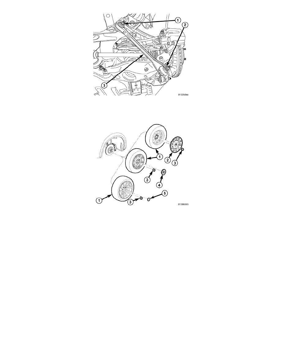
1. Position link and install bolt and nut (1) mounting link (3) at crossmember. Do not tighten bolt at this time.
2. Install bolt and nut (2) mounting link (3) at knuckle. Do not tighten bolt at this time.
3. Install tire and wheel assembly (1). Tighten wheel mounting nuts (3) to 150 Nm (110 ft. lbs.) (Police - 190 Nm (140 ft. lbs.)). See: Wheels and
Tires/Service and Repair/Removal and Replacement/Tires and Wheels - Installation
4. Lower vehicle.
5. Position vehicle on alignment rack/drive-on lift. Raise vehicle as necessary to access link fasteners.
6. Tighten compression link fasteners to:
-
Bolt at crossmember - 85 Nm (63 ft. lbs.).
-
Bolt at knuckle - 81 Nm (60 ft. lbs.).
7. Perform wheel alignment. See: Alignment/Service and Repair
Rear Suspension - Spring Link - Removal
SPRING LINK - SRT8
1. Access and remove rear brake rotor on side of repair. See: Brakes and Traction Control/Disc Brake System/Brake Rotor/Disc/Service and
Repair/Removal and Replacement/Brake Rotor - Removal
2. Access and remove rear spring on side of repair. See: Suspension Spring ( Coil / Leaf )/Service and Repair/Rear Suspension - Coil Spring(s) -
Removal