
Colt L4-089 1468cc 1.5L VIN K 2-bbl (1988)
Camshaft: Service and Repair
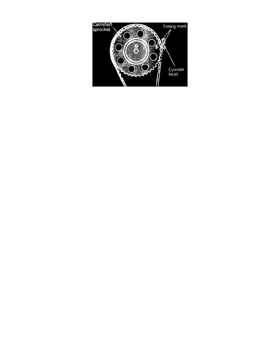
Fig. 9 Camshaft timing marks. 1500cc engine
REMOVAL
1.
Disconnect battery ground cable.
2.
Disconnect breather hose and secondary air hose.
3.
Remove air cleaner and the timing belt cover.
4.
Rotate crankshaft in normal direction of rotation to bring No. 1 cylinder to top dead center compression stroke. The No. 1 cylinder is at top dead
center compression stroke when the mark on the upper timing under cover is aligned with the mark on the camshaft sprocket, Fig. 9.
5.
Move timing belt tensioner fully toward the water pump assembly and temporarily secure it.
6.
Remove camshaft sprocket attaching bolt, then detach sprocket from camshaft with timing belt attached. Position camshaft sprocket on lower belt
cover or suspend sprocket and belt from hood to maintain proper timing alignment. Do not rotate crankshaft after removing sprocket from
camshaft.
7.
Remove rocker cover, and note position of camshaft.
8.
Remove rocker shaft assembly and cylinder head rear cover.
9.
Remove camshaft thrust case tightening bolt, thrust case and camshaft. Remove assembly toward transaxle side of cylinder head.
INSTALLATION
1.
Check camshaft journals for wear. If journals are badly worn, replace camshaft.
2.
Install camshaft thrust case and thrust plate to camshaft end and firmly tighten attaching bolt. Check camshaft endplay. Endplay should be 0.002 -
0.008 inch. If endplay exceeds specified value, replace thrust case and recheck endplay.
3.
If endplay is still not within specification, check rear end of camshaft journal for wear. If badly worn, replace camshaft.
4.
Lubricate camshaft journal and thrust portions of camshaft with clean engine oil.
5.
Insert camshaft into cylinder head and rotate camshaft to position noted during disassembly (TDC on compression stroke for No. 1 cylinder).
6.
Insert camshaft thrust case with the threaded hole facing upward. Align threaded hole with bolt hole in the cylinder head. Install and firmly tighten
attaching bolt.
7.
Install rear gasket and cover. Firmly tighten bolts.
8.
Install camshaft oil seal. Lubricate external surface of seal completely with engine oil.
9.
Ensure seal is completely seated.
10.
Install camshaft sprocket and timing belt, and ensure timing marks are aligned, Fig. 9. Torque bolt to 47-54 ft. lbs.
11.
Install rocker arm and shaft assembly.
12.
Temporarily set valve clearances to specifications with the engine cold.
13.
Install gasket in rocker cover groove, then temporarily install rocker cover.
14.
Start and operate engine at idle speed until normal operating temperature is reached and adjust valve clearances. With engine hot, adjust jet valve
clearance to specifications.
15.
Install rocker cover.
16.
Reverse remaining procedure to complete installation.