
Dakota 4WD V8-4.7L VIN N (2000)
Glove Compartment: Service and Repair
Glove Box Bin Replacement
The only serviced component of the glove box is the glove box bin. If any other component of the glove box is faulty or damaged, the entire glove box
assembly must be replaced.
WARNING: ON VEHICLES EQUIPPED WITH AIR-BAGS, REFER TO AIRBAGS AND SEAT BELTS/AIRBAGS BEFORE
ATTEMPTING ANY STEERING WHEEL, STEERING COLUMN, OR INSTRUMENT PANEL COMPONENT DIAGNOSIS OR SERVICE.
FAILURE TO TAKE THE PROPER PRECAUTIONS COULD RESULT IN ACCIDENTAL AIR-BAG DEPLOYMENT AND POSSIBLE
PERSONAL INJURY.
REMOVAL
GLOVE BOX BIN
1. Disconnect and isolate the battery negative cable.
2. Remove the glove box from the instrument panel. Refer to Glove Box - Removal in the Removal and Installation for the procedures.
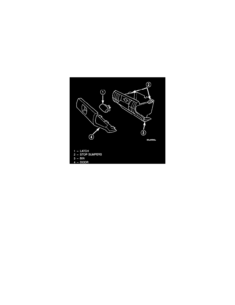
Glove Box Components Remove/Install
3. Remove the two screws that secure each outboard flange of the glove box bin to the glove box door.
4. Remove the two remaining screws in the bottom of the glove box bin (the center screw was removed during glove box removal) that secure the
bin to the bottom of the glove box door.
5. Remove the four screws that secure the top of the glove box bin and the glove box latch to the glove box door.
6.
Remove the glove box bin and the glove box latch from the glove box door.
INSTALLATION
GLOVE BOX BIN
1. Position the glove box latch and the glove box bin to the glove box door.
2. Install and tighten the four screws that secure the top of the glove box bin and the glove box latch to the glove box door. Tighten the screws to
2.2 Nm (20 in. lbs.).
3. Install and tighten the two outboard screws in the bottom of the glove box bin (the center screw will be installed following glove box
installation) that secure the bin to the bottom of the glove box door. Tighten the screws to 2.2 Nm (20 in. lbs.).
4. Install and tighten the two screws that secure each outboard flange of the glove box bin to the glove box door. Tighten the screws to 2.2 Nm
(20 in. lbs.).
5. Install the glove box onto the instrument panel. Refer to Glove Box-Installation in the Removal and Installation for the procedures.
6. Reconnect the battery negative cable.