
Dakota Quad Cab 2WD V8-5.9L VIN Z LDC (2002)
Central Timer Module ( CTM ) Low Option: Service and Repair
WARNING: ON VEHICLES EQUIPPED WITH AIRBAGS, DISABLE THE AIRBAG SYSTEM BEFORE ATTEMPTING ANY
STEERING WHEEL, STEERING COLUMN, SEAT BELT TENSIONER, OR INSTRUMENT PANEL COMPONENT DIAGNOSIS OR
SERVICE. DISCONNECT AND ISOLATE THE BATTERY NEGATIVE (GROUND) CABLE, THEN WAIT TWO MINUTES FOR THE
AIRBAG SYSTEM CAPACITOR TO DISCHARGE BEFORE PERFORMING FURTHER DIAGNOSIS OR SERVICE. THIS IS THE
ONLY SURE WAY TO DISABLE THE AIRBAG SYSTEM. FAILURE TO TAKE THE PROPER PRECAUTIONS COULD RESULT IN
ACCIDENTAL AIRBAG DEPLOYMENT AND POSSIBLE PERSONAL INJURY.
REMOVAL
NOTE: Before replacing a Central Timer Module (CTM), use a DRB III scan tool to retrieve the current settings for the CTM programmable
features. Refer to the appropriate diagnostic information. These settings should be duplicated in the replacement CTM using the DRB III scan tool
before returning the vehicle to service.
1. Disconnect and isolate the battery negative cable.
2. Remove the trim from the left cowl inner panel.
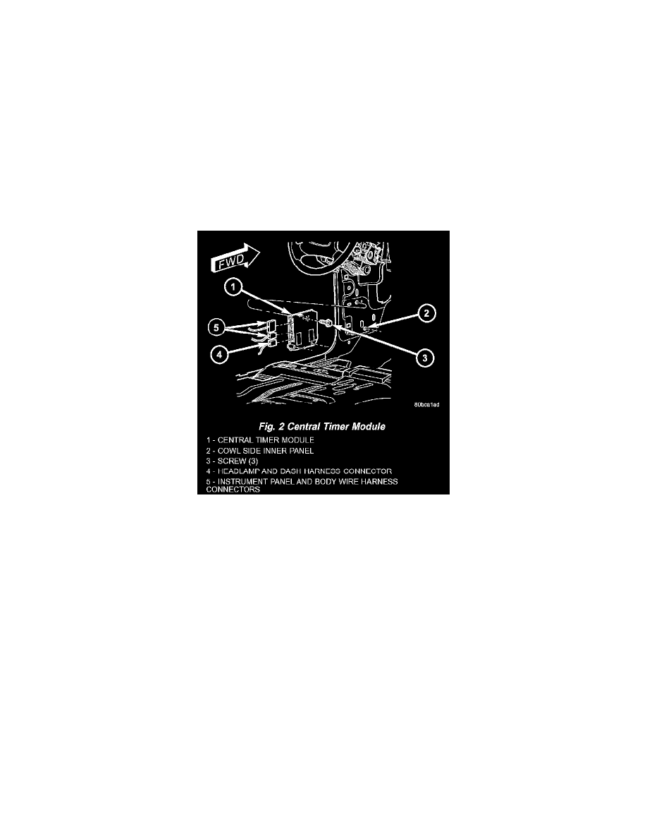
Fig.2 Central Timer Module
3. Disconnect the wiring harness connectors from the CTM. (Fig. 2).
4. Remove the screws that secure the CTM to the left cowl inner panel.
5. Remove the CTM from the left cowl inner panel.
INSTALLATION
NOTE: Before replacing a Central Timer Module (CTM), use a DRB III scan tool to retrieve the current settings for the CTM programmable
features. Refer to the appropriate diagnostic information. These settings should be duplicated in the replacement high-line/premium CTM using the
DRB III scan tool before returning the vehicle to service.
1. Position the CTM onto the left cowl inner panel (Fig. 2).
2. Install and tighten the screws that secure the CTM to the left cowl inner panel. Tighten the screws to 2 Nm (20 in. lbs.).
3. Reconnect the wiring harness connectors to the CTM.
4. Reinstall the trim onto the left cowl side inner panel.
5. Reconnect the battery negative cable.