
Durango 2WD V8-5.2L VIN Y (1999)
Fuse Block: Service and Repair
Junction Block Replacement
WARNING: ON VEHICLES EQUIPPED WITH AIR-BAGS, REFER TO RESTRAINT SYSTEMS BEFORE ATTEMPTING ANY
STEERING WHEEL, STEERING COLUMN, OR INSTRUMENT PANEL COMPONENT DIAGNOSIS OR SERVICE. FAILURE TO TAKE
THE PROPER PRECAUTIONS COULD RESULT IN ACCIDENTAL AIR-BAG DEPLOYMENT AND POSSIBLE PERSONAL INJURY.
REMOVAL
1. Disconnect and isolate the battery negative cable.
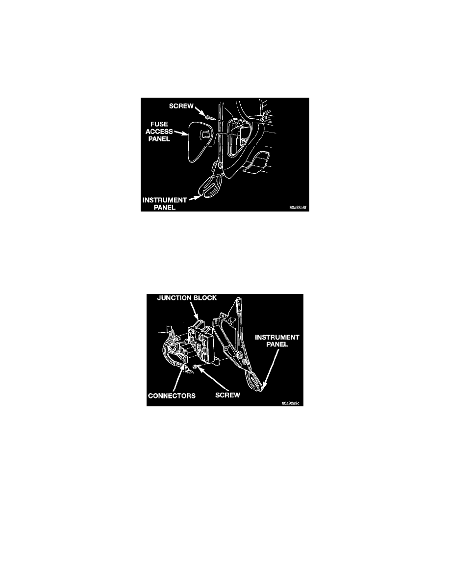
Fuse Access Panel Remove/Install
2. Remove the fuse access panel by unsnapping it from the left outboard end of the instrument panel.
3. Reaching through the instrument panel fuse access panel opening, remove the one screw that secures the junction block to the left instrument panel
end bracket.
4. Remove the steering column opening cover from the instrument panel. Refer to Steering Column Opening Cover/Service and Repair of Instrument
Panel Systems for the procedures.
5. Reach through the outboard side of the instrument panel steering column opening to access the junction block.
Junction Block Remove/Install
6. Disconnect all of the wire harness connectors from the connector receptacles on the back of the junction block.
7. Still reaching through the instrument panel steering column opening, remove the relay and fuse block from the junction block. Push the relay and
fuse block towards the left end of the instrument panel to disengage its mounting slots from the tabs on the junction block.
8. Still reaching through the outboard side of the instrument panel steering column opening, remove the one screw that secures the junction block to
the left instrument panel end bracket.
9. Remove the junction block from the left instrument panel end bracket.
INSTALLATION
NOTE: If the Junction Block (JB) is being replaced with a new unit, be certain to transfer each of the fuses, circuit breakers and relays from the
old JB to the proper cavities of the new JB.
1. Position the junction block onto the left instrument panel end bracket.
2. Install and tighten the one screw that secures the junction block to the left instrument panel end bracket. Tighten the screw to 2.2 Nm (20 in. lbs.).
3. Install the relay and fuse block onto the junction block by engaging its mounting slots with the tabs on the junction block.
4. Reconnect all of the wire harness connectors to the connector receptacles on the back of the junction block.