
Durango 2WD V8-5.2L VIN Y (1999)
Auxiliary Power Outlet: Service and Repair
WARNING: ON VEHICLES EQUIPPED WITH AIR-BAGS, REFER TO AIRBAG AND SEAT BELTS/AIR BAGS BEFORE
ATTEMPTING ANY STEERING WHEEL, STEERING COLUMN, OR INSTRUMENT PANEL COMPONENT DIAGNOSIS OR SERVICE.
FAILURE TO TAKE THE PROPER PRECAUTIONS COULD RESULT IN ACCIDENTAL AIR-BAG DEPLOYMENT AND POSSIBLE
PERSONAL INJURY.
REMOVAL
1. Disconnect and isolate the battery negative cable.
2. Remove the lower bezel from the instrument panel. Refer to Instrument Panel Lower Bezel/Service and Repair for the procedures.
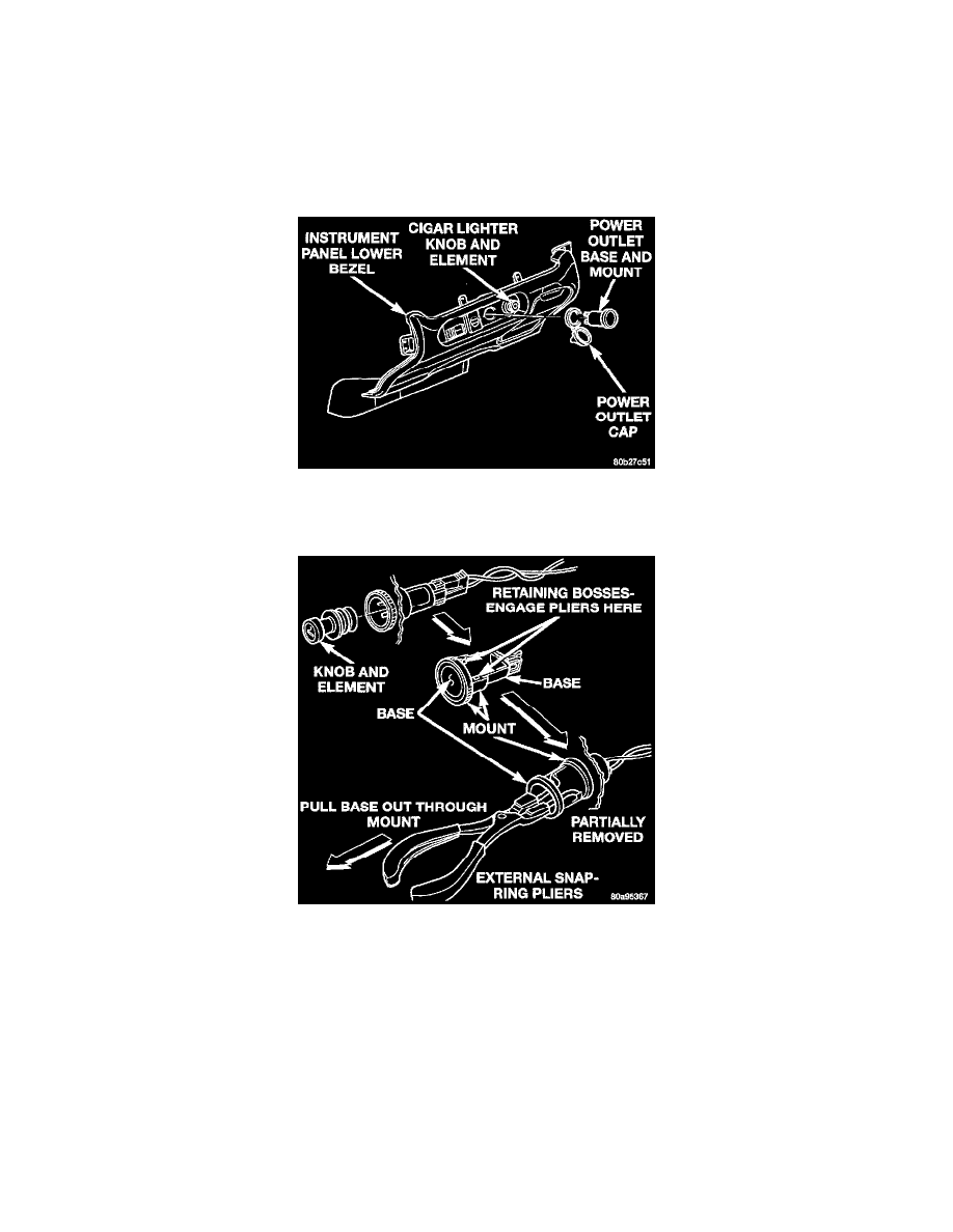
Instrument Panel Cigar Lighter And Power Outlet
3. Pull the cigar lighter knob and element out of the cigar lighter receptacle base, or unsnap the protective cap from the power outlet receptacle base.
Cigar Lighter And Power Outlet Remove/Install - Typical
4. Look inside the cigar lighter or power outlet receptacle base and note the position of the rectangular retaining bosses of the mount that secures the
receptacle base to the instrument panel lower bezel.
5. Insert a pair of external snap ring pliers into the cigar lighter or power outlet receptacle base and engage the tips of the pliers with the retaining
bosses of the mount.
6. Squeeze the pliers to disengage the mount retaining bosses from the receptacle base and, using a gentle rocking motion, pull the pliers and the
receptacle base out of the mount.
7. Remove the cigar lighter or power outlet mount from the instrument panel lower bezel.
INSTALLATION
1. Install the cigar lighter or power outlet mount into the instrument panel lower bezel.
2. Align the splines on the outside of the cigar lighter or power outlet receptacle base connector receptacle with the grooves on the inside of the
mount.
3. Press firmly on the cigar lighter or power outlet receptacle base until the retaining bosses of the mount are fully engaged in their receptacles.