
Durango 4WD V8-5.9L VIN Z (1998)
Hydraulic Control Assembly - Antilock Brakes: Description and Operation
Hydraulic Control Unit (HCU)
Description
The HCU on the EBC 2 has only a separate rear valve body.
The HCU on the EBC 325 has two integral valve bodies for controlling the front and rear brakes.
Within the HCU are solenoids, valves, check valves, and a reset switch necessary to apply and release brake pressure as required to avoid wheel lockup,
keep the wheels rolling, and maintain optimum deceleration.
The isolation valve is normally open, allowing unrestricted flow from the master cylinder to the wheels. When the CAB determines antilock intervention
is required, the valve closes to isolate the master cylinder hydraulic circuit. Fluid is trapped in the circuit and then prevented from reaching the wheels.
The dump valve is pulsed on and off by the CAB. This valve cycles only if the isolation valve is closed. When dump is on, it allows fluid to the low
pressure accumulator for temporary storage. This causes the pressure to the wheel to decrease. When the valve is off, fluid is allowed to the wheel.
The brake return check valve allows the HCU to drain faster after the ABS stop, when the brake is released.
The Reset Switch is positioned in the HCU to monitor the master cylinder (input), rear brake (output) and accumulator pressure. During normal braking,
pressure is equal for input and output and the switch remains open. During an Antilock stop the switch will close as the isolation valve is cycled and
pressure becomes unequal between input and output. At the end of an ABS stop the isolation valve will open as master cylinder pressure and rear
pressure equalize. The switch is used to monitor correct operation of the HCU and to set a diagnostic trouble code if incorrect pressure is detected.
When the brakes are applied, fluid is forced from the master cylinder outlet ports to the HCU inlet ports. This pressure is transmitted through three
normally open isolation valves inside the HCU, then through the outlet ports of the HCU to the wheels. If the CAB senses that a wheel is about to lock,
based on wheel speed sensor data, it pulls the normally open isolation valve closed for that circuit. This prevents any more fluid from entering that
circuit. The CAB continues to look at the sensor signal to determine if the wheel is still decelerating. If deceleration is still taking place, the normally
closed dump valve for that circuit is opened. This dumps any pressure that is trapped between the normally open valve and the brake back into an
accumulator. Once the affected circuit comes back up to speed, the CAB returns the valves to their normal condition allowing the affected brake to be
reapplied. On the EBC 325 system, the pump and accumulators are used to provide rapid response during the reapply sequence and to minimize pedal
feedback.
With Four Wheel Antilock Brakes
GENERAL INFORMATION
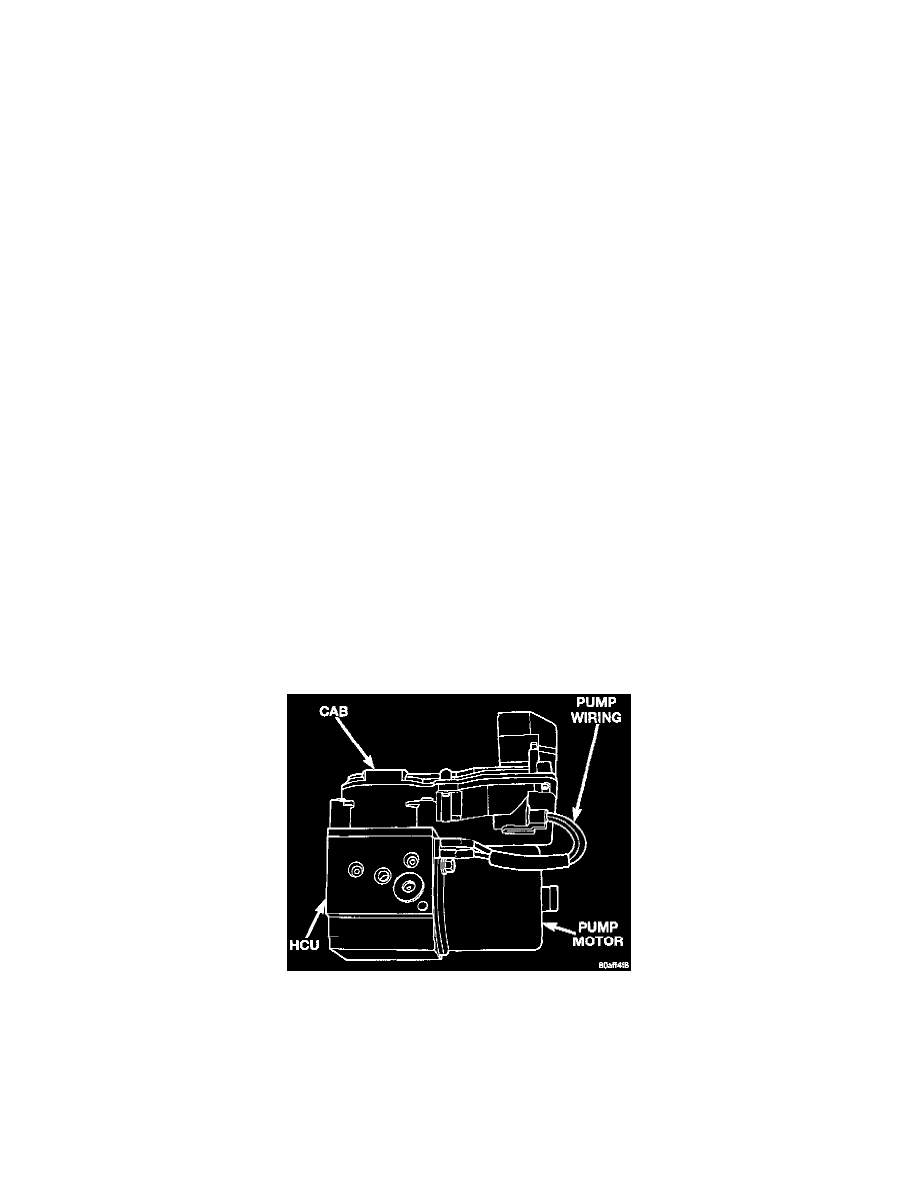
CAB/HCU
The Hydraulic Control Unit (HCU) consists of a valve body, pump, accumulator and motor.
The pump, motor, and accumulator are combined into an assembly attached to the valve body. The accumulator store the extra fluid which had to
be dumped from the brakes. This is done to prevent the wheels from locking up. The pump provides the fluid volume needed and is operated by a
DC type motor. The motor is controlled by the Controller Antilock Brake (CAB).
The valve body contains the solenoid valves. The valves modulate brake pressure during antilock braking and are controlled by the CAB.