
Durango 4WD V8-5.9L VIN Z (1998)
Coolant Temperature Sensor/Switch (For Computer): Testing and Inspection
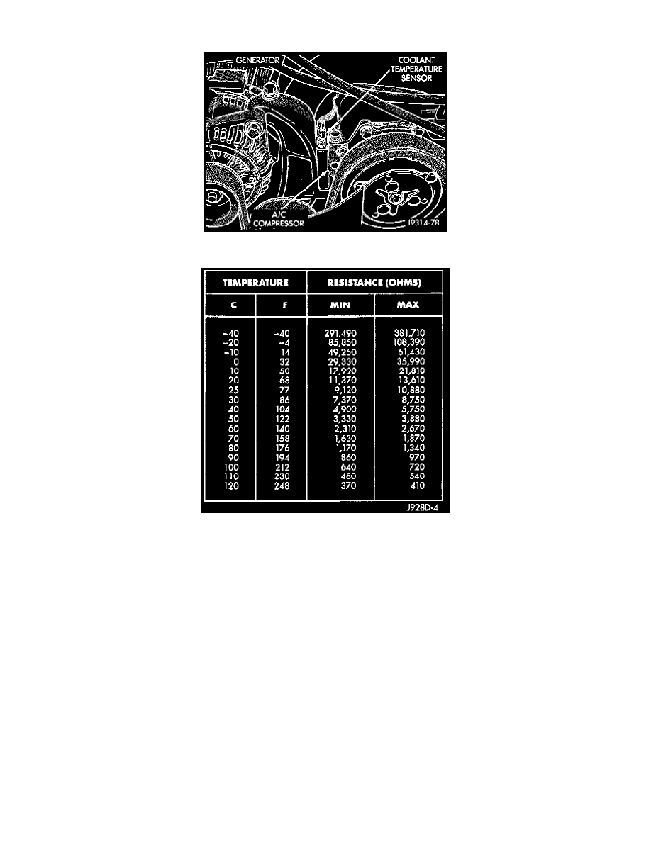
Fig 57 Engine Coolant Temperature Sensor - Typical
Sensor Resistance Chart (OHMS)
To perform a complete test of the engine coolant temperature sensor and its circuitry, refer to Powertrain Management/Computers and Controls/Testing
and Inspection/Procedures/Diagnostic Charts. To test the sensor only, refer to the following:
1. Disconnect wire harness connector from coolant temperature sensor (Fig. 57).
2. Engines with air conditioning:
-
When removing the connector from sensor, do not pull directly on wiring harness.
-
Fabricate an L-shaped hook tool from a coat hanger (approximately eight inches long).
-
Place the hook part of tool under the connector for removal.
-
The connector is snapped onto the sensor.
-
It is not equipped with a lock type tab.
3. Test the resistance of the sensor with a high input impedance (digital) volt-ohmmeter.
-
The resistance (as measured across the sensor terminals) should be as shown in the Coolant Temperature Sensor/Intake Air Temperature
Sensor resistance chart.
-
Replace the sensor if it is not within the range of resistance specified in the chart.
4. Test continuity of the wire harness between the PCM wire harness connector and the coolant sensor connector terminals.
-
Diagrams/Electrical/Connector Views for terminal/cavity locations.
-
Repair the wire harness if an open circuit is indicated.
5. After tests are completed, connect electrical connector to sensor.
-
The sensor connector is symmetrical (not indexed).
-
It can be installed to the sensor in either direction.