
Grand Caravan V6-3.3L VIN E Flex Fuel (2007)
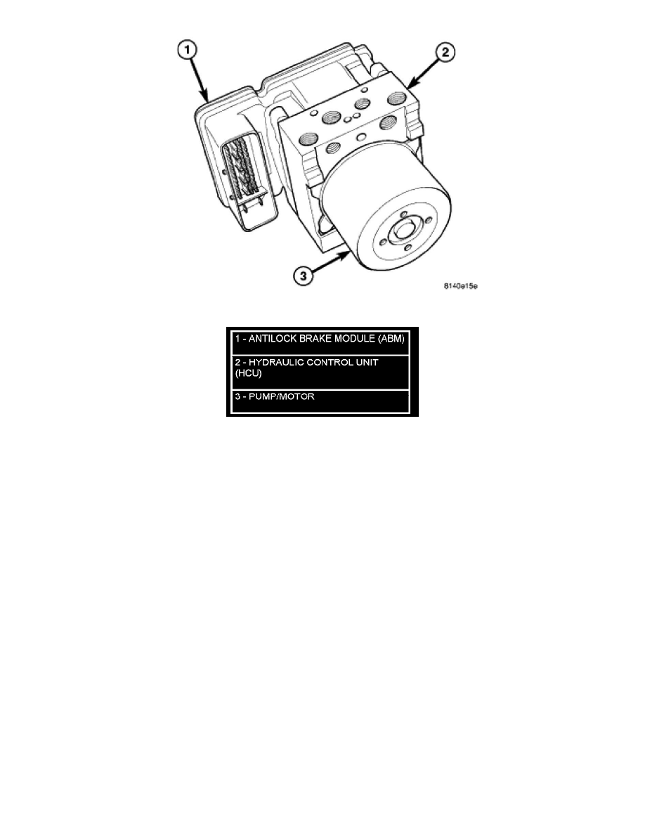
Figure 1 Integrated Control Unit
Hydraulic Circuits And Valves - Mk20E
HYDRAULIC CIRCUITS AND VALVES - MK20E
NOTE: The following applies to Mark 20e ABS only and is only used on right-hand-drive (RHD) vehicles.
The hydraulic fluid control valves control the flow of pressurized brake fluid to the wheel brakes during the different modes of ABS braking. The
following paragraphs explain how this works. For purposes of explanation only, it is assumed that only the right front wheel is experiencing antilock
braking; the following diagrams show only the right front wheel in an antilock braking operation.
NORMAL BRAKING HYDRAULIC CIRCUIT AND SOLENOID VALVE FUNCTION
The hydraulic diagram (Figure 1) shows the vehicle in the normal braking mode of the base brake hydraulic system. The diagram shows no wheel spin or
slip occurring relative to the speed of the vehicle. The driver is applying the brake pedal which builds pressure in the brake hydraulic system to engage
the brakes and stop the vehicle.