
Grand Caravan V6-3.3L VIN E Flex Fuel (2007)
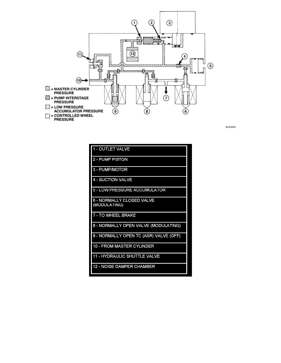
Figure 4 Hydraulic Circuit - ABS Braking Mode (With Traction Control)
ABS TRACTION CONTROL HYDRAULIC CIRCUIT, SOLENOID VALVE, AND SHUTTLE VALVE FUNCTION (ABS WITH
TRACTION CONTROL)
The hydraulic diagram shows the vehicle in the traction control (TC) mode (Figure 5). The diagram shows a drive wheel is spinning and brake pressure
is required to reduce its speed.
-
The normally open TC (ASR) valve is energized to isolate the brake fluid being pumped from the master cylinder and to isolate the driven wheel.
-
The normally open TC (ASR) valve bypasses the pump output back to the master cylinder at a fixed pressure setting.
-
The normally open and normally closed valves modulate (build/decay) the brake pressure as required to the spinning wheel.