
Grand Caravan V6-3.3L VIN R (2005)
Hydraulic Control Assembly - Antilock Brakes: Description and Operation
Integrated Control Unit (ICU)
MK20E
INTEGRATED CONTROL UNIT (ICU) MK20E
DESCRIPTION
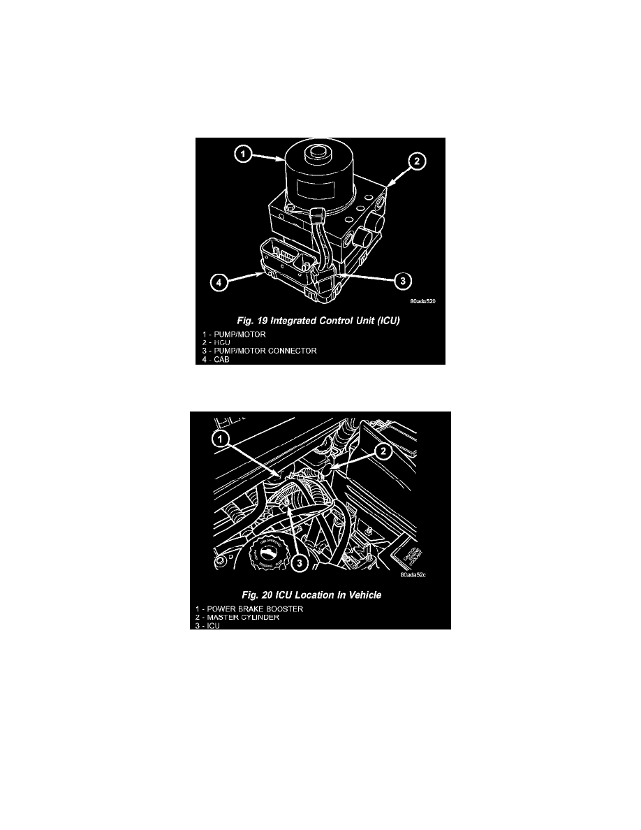
The hydraulic control unit (HCU) and the controller antilock brake (CAB) used with this antilock brake system are combined (integrated) into one
unit, which is called the integrated control unit (ICU) (Fig. 19).
Depending on whether the vehicle is Left-Hand Drive (LHD) or Right-Hand-Drive (RHD), the integrated control unit (ICU) is located in one of two
locations. On LHD models, the ICU (and mounting bracket) is mounted to the front suspension cradle/crossmember below the master cylinder (Fig.
20). On RHD models, the ICU is located behind the front suspension cradle/crossmember on the left side of the vehicle.
Two different ICU's (HCU and CAB) are used on this vehicle depending on whether or not the vehicle is equipped with traction control. The HCU on
a vehicle equipped with traction control has a valve block that is approximately one inch longer than a HCU on a vehicle that is equipped with ABS
only.
The ABS-only ICU consists of the following components: the CAB, eight (build/decay) solenoid valves (four inlet valves and four outlet valves),
valve block, fluid accumulators, a pump, and an electric motor.
The ABS-with traction control ICU consists of the following components: the CAB, eight (build/decay) solenoid valves (four inlet valves and four
outlet valves), two traction control (ASR) valves, two hydraulic shuttle valves, valve block, fluid accumulators, a pump, and an electric motor.