
Grand Caravan V6-3.8L (2009)
Collision Avoidance Sensor: Description and Operation
Blind Spot Sensor - Description
DESCRIPTION
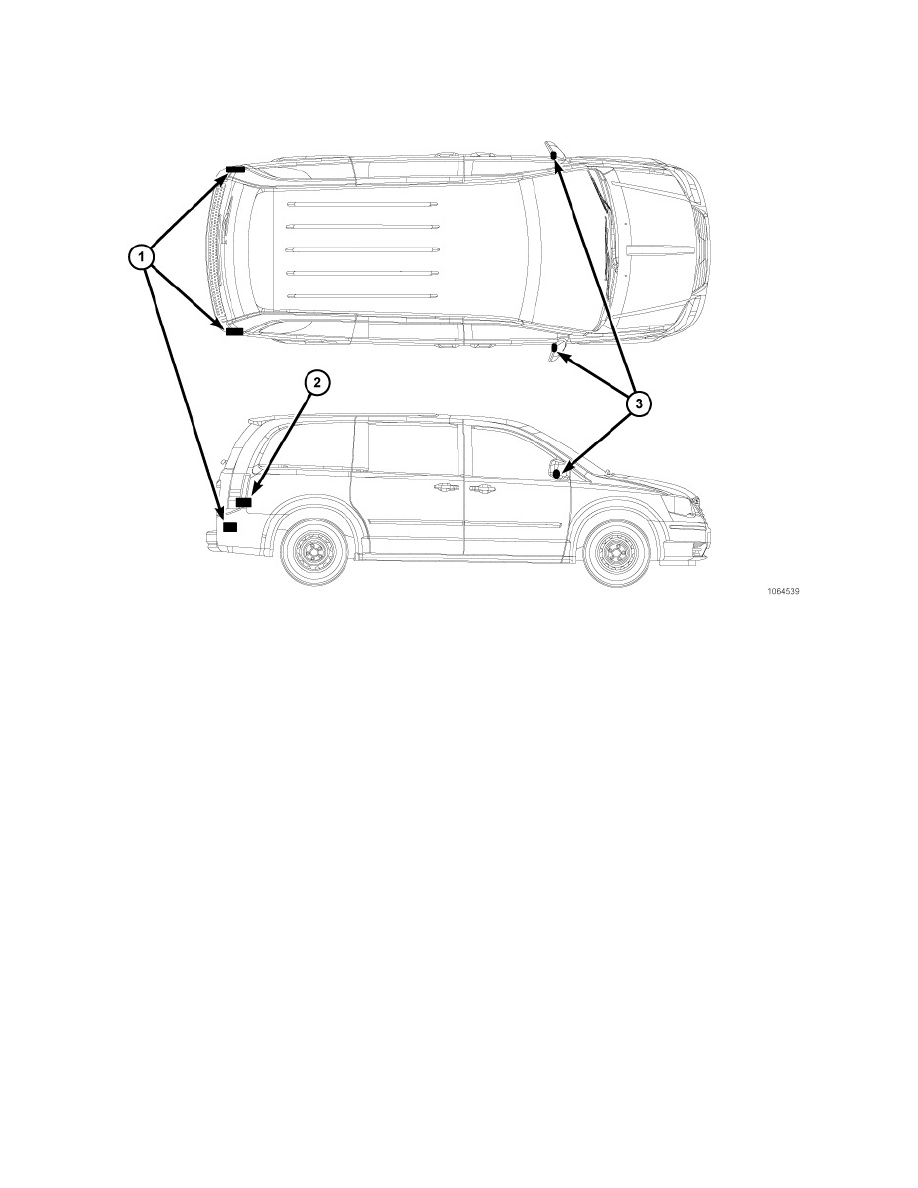
Blind Spot Sensors (1) - Vehicles equipped with the blind spot system have two radar blind spot sensors that are concealed behind the rear bumper
fascia. Each sensor is snapped into an individual molded plastic mounting bracket secured at horizontal intervals located on the back side of the rear
bumper fascia directly below the left and right tail lamps.
Hardwired circuitry connects the various blind spot monitor system components to each other through the electrical system of the vehicle. These
hardwired circuits are integral to several wire harnesses, which are routed throughout the vehicle and retained by many different methods. These circuits
may be connected to each other and to the vehicle electrical system through the use of a combination of soldered splices, splice block connectors, and
many different types of wire harness terminal connectors and insulators. Refer to the appropriate wiring information. The wiring information includes
wiring diagrams, proper wire and connector repair procedures, further details on wire harness routing and retention, as well as pin-out and location views
for the various wire harness connectors, splices and grounds.
The blind spot monitor system components cannot be adjusted or repaired. If any of the BSM system components are damaged or inoperative, that
component must be replaced. For more information on the blind spot monitor system and its components See: Instrument Panel, Gauges and Warning
Indicators/Audible Warning Device/Description and Operation/Chime/Buzzer - Description