
Grand Caravan FWD V6-181 3.0L SOHC (1993)
Throttle Body: Testing and Inspection
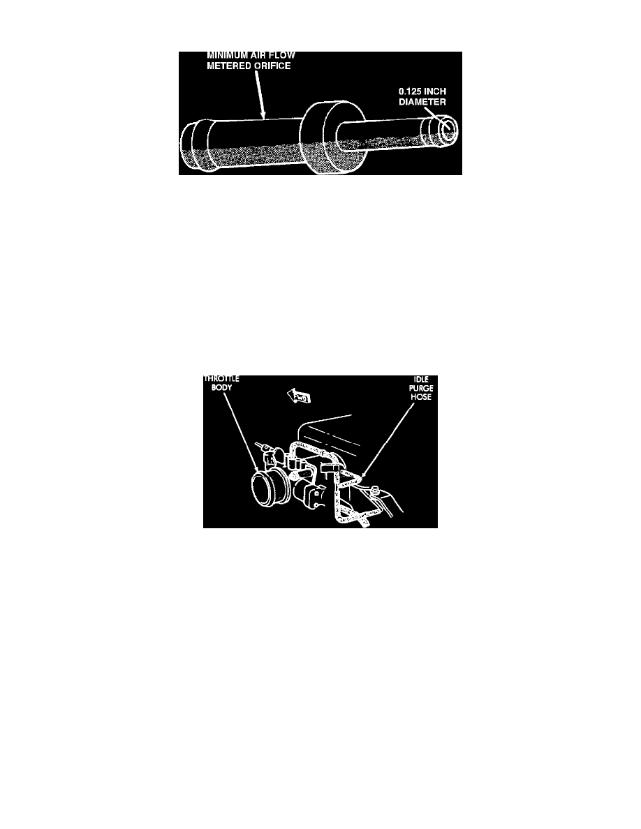
Minimum Air Flow Air Metering Fitting
WARNING: Apply parking brake and/or block wheels before performing any engine running test with the vehicle on the ground.
NOTE: Before performing minimum air flow test, make sure all accessories are off.
1. With vehicle in PARK (A/T) or NEUTRAL (M/T), START the engine and allow it to warm up until the cooling fan cycles at least once, then shut
OFF the engine.
2. Connect a timing light and tachometer to the engine.
3. Disconnect the coolant temperature sensor and START the engine. Adjust basic timing to 12° BTDC +/- 2°, then shut OFF the engine and connect
the coolant temperature sensor.
4. Disconnect the PCV valve hose from the PCV valve and plug the PCV valve nipple.
Idle Purge Hose
5. Disconnect the idle purge hose from the engine vacuum harness tee and install a 0.125" orifice tube (Miller Tool# 6457 or equivalent) in the intake
manifold mounted idle purge hose.
6. Connect the scan tool to the engine compartment Data Link Connector (DLC). START the engine and allow it to idle for at least one minute.
7. Using the scan tool, access the MINIMUM AIRFLOW IDLE SPEED TEST. When this mode is entered, the following will occur:
-
The Idle Air Control (IAC) motor should close the bypass passage fully.
-
Idle spark advance should become fixed.
-
Idle fuel should become fixed.
-
Engine rpm will be displayed on the scan tool.
8. Check the idle rpm with a tachometer.
-
If idle rpm is within range, Minimum Air Flow is set correctly.
-
If idle rpm is not within specified range, clean throttle body and retest. SEE Powertrain Management/Fuel Delivery and Air Induction
/Service and Repair.
9. Shut OFF the engine; remove the scan tool, tachometer, timing light, and orifice tube; and connect the purge line and PCV valve to their respective
ports.
10. Erase any fault codes that may have been set.