
Intrepid V6-2.7L VIN R (2003)
Hydraulic Control Assembly - Antilock Brakes: Description and Operation
Hydraulic/Mechanical
HYDRAULIC/MECHANICAL
OPERATION - HYDRAULIC CIRCUITS AND VALVES
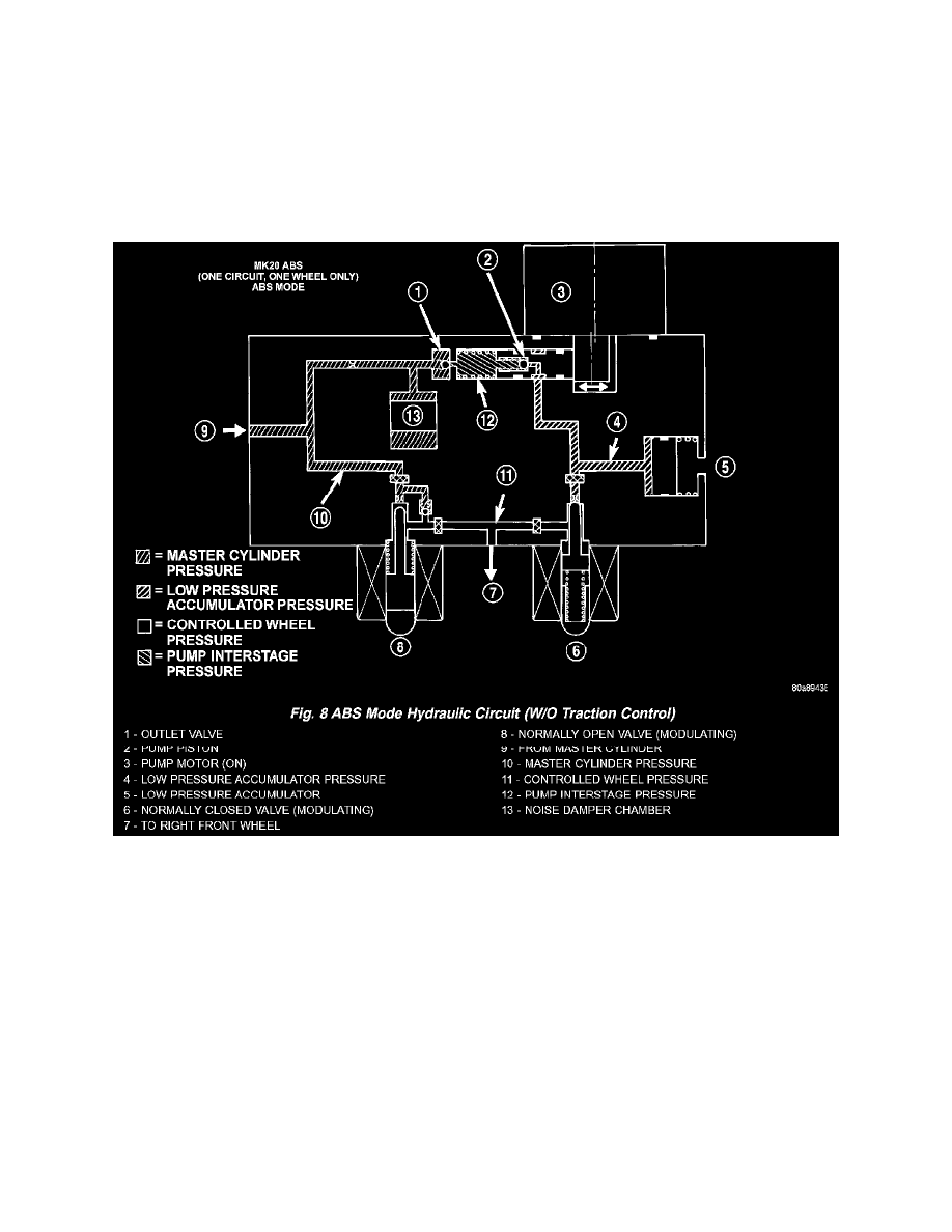
The hydraulic fluid control valves within the HCU control the flow of pressurized brake fluid to the wheel brakes during the different modes of ABS
braking. The following paragraphs explain how this works. For purposes of explanation only, it is assumed that only the right front wheel is
experiencing antilock braking; the following diagrams show only the right front wheel in an antilock braking operation.
ABS HYDRAULIC CIRCUIT AND SOLENOID VALVE FUNCTION (ABS WITHOUT TRACTION CONTROL)
The hydraulic diagram shows the vehicle in the ABS braking mode. The diagram shows one wheel is slipping because the driver is attempting to stop
the vehicle at a faster rate than is allowed by the surface on which the tires are riding.
-
The normally open and normally closed valves modulate (build/decay) the brake hydraulic pressure as required.
-
The pump/motor is switched on so that the brake fluid from the low pressure accumulators is returned to the master cylinder circuits.
-
The brake fluid is routed to either the master cylinder or the wheel brake depending on the position of the normally open valve.
NORMAL BRAKING HYDRAULIC CIRCUIT, SOLENOID VALVE FUNCTION (ABS WITHOUT TRACTION CONTROL)