
Intrepid V6-2.7L VIN R (2003)
Ignition Off-Draw (IOD) Fuse: Testing and Inspection
STANDARD PROCEDURE - IGNITION-OFF DRAW TEST
The term Ignition-Off Draw (IOD) identifies a normal condition where power is being drained from the battery with the ignition switch in the OFF
position. A normal vehicle electrical system will draw from 5 - 35 milliamperes (0.005 - 0.035 ampere) with the ignition switch in the OFF position,
and all non-ignition controlled circuits in proper working order. Up to 35 milliamperes are needed to enable the memory functions for the Powertrain
Control Module (PCM), digital clock, electronically tuned radio, and other modules which may vary with the vehicle equipment.
A vehicle that has not been operated for approximately 20 days, may discharge the battery to an inadequate level. When a vehicle will not be used for
twenty days or more (stored), remove the IOD fuse from the Junction Block (JB). This will reduce battery discharging.
Excessive IOD can be caused by:
-
Electrical items left on.
-
Faulty or improperly adjusted switches.
-
Faulty or shorted electronic modules and components.
-
An internally shorted generator.
-
Intermittent shorts in the wiring.
If the IOD is over 35 milliamperes, the problem must be found and corrected before replacing a battery In most cases, the battery can be charged and
returned to service after the excessive IOD condition has been corrected.
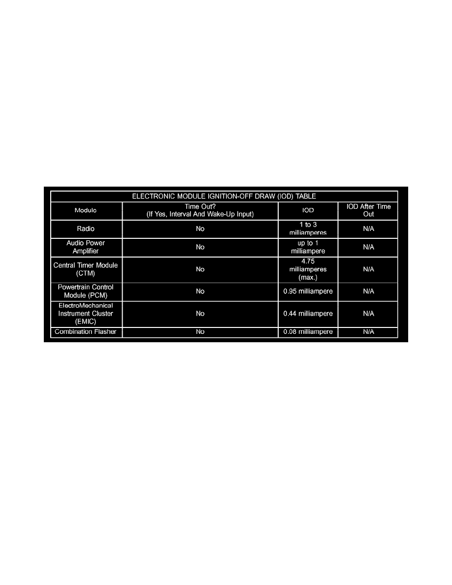
Electronic Module Ignition-Off Draw (IOD) Table
1. Verify that all electrical accessories are OFF. Turn OFF all lamps, remove the ignition key, and close all doors. If the vehicle is equipped with an
illuminated entry system or an electronically tuned radio, allow the electronic timer function of these systems to automatically shut off (time out).
This may take up to 3 minutes. See the Electronic Module Ignition-Off Draw Table for more information.
2. Determine that the underhood lamp is operating properly then disconnect the lamp wire harness connector or remove the lamp bulb.
3. Disconnect the battery negative cable.
4. Set an electronic digital multi-meter to its highest amperage scale. Connect the multi-meter between the disconnected battery negative cable
terminal clamp and the battery negative terminal post. Make sure that the doors remain closed so that the illuminated entry system is not activated.
The multi-meter amperage reading may remain high for up to 3 minutes, or may not give any reading at all while set in the highest amperage
scale, depending upon the electrical equipment in the vehicle. The multi-meter leads must be securely clamped to the battery negative cable
terminal clamp and the battery negative terminal post. If continuity between the battery negative terminal post and the negative cable terminal
clamp is lost during any part of the IOD test, the electronic timer function will be activated and all of the tests will have to be repeated.
5. After about 3 minutes, the high-amperage IOD reading on the multi-meter should become very low or nonexistent, depending upon the electrical
equipment in the vehicle. If the amperage reading remains high, remove and replace each fuse or circuit breaker in the Power Distribution Center (
PDC) and then in the Junction Block (JB), one at a time until the amperage reading becomes very low, or nonexistent. Refer to the appropriate
wiring information for complete PDC and JB fuse, circuit breaker, and circuit identification. This will isolate each circuit and identify the circuit
that is the source of the high-amperage IOD. If the amperage reading remains high after removing and replacing each fuse and circuit breaker,
disconnect the wire harness from the generator. If the amperage reading now becomes very low or nonexistent, refer to Charging System for the
proper charging system diagnosis and testing procedures. After the high-amperage IOD has been corrected, switch the multi-meter to progressively
lower amperage scales and, if necessary, repeat the fuse and circuit breaker remove-and-replace process to identify and correct all sources of
excessive IOD. It is now safe to select the lowest milliampere scale of the multi-meter to check the low-amperage IOD.
CAUTION: Do not open any doors, or turn on any electrical accessories with the lowest milliampere scale selected, or the multi-meter may be
damaged.