
Journey AWD V6-3.5L (2009)
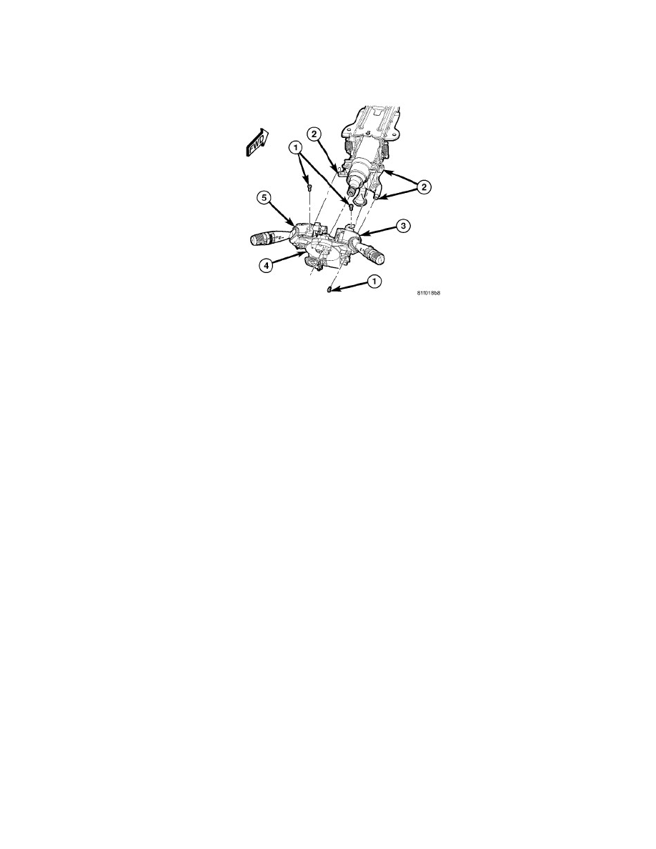
1. If a new clockspring (1) is being installed, transfer the multifunction switch jumper harness from the old clockspring or position a new jumper
harness onto the new clockspring.
2. Carefully slide the clockspring down over the steering column upper shaft far enough to reconnect the three instrument panel wire harness
connectors (2) to the receptacles on the back of the clockspring case.
3. Position the clockspring (4) onto the steering column bracket (2).
4. Install and tighten the three screws (1) that secure the clockspring to the bracket in the following sequence: lower right, upper left, upper right.
Tighten the screws to 3 Nm (27 in. lbs.).
NOTE: Use of an improper sequence when tightening the clockspring mounting screws may result in an audible ticking noise as the steering
wheel is rotated.
5. Reinstall the left multi-function switch (5) onto the clockspring. See: Lighting and Horns/Sensors and Switches - Lighting and Horns/Combination
Switch/Service and Repair/Left Multifunction Switch - Installation.
6. Reinstall the right multi-function switch (3) onto the clockspring. See: Sensors and Switches/Sensors and Switches - Wiper and Washer
Systems/Wiper Switch/Service and Repair/Right Multifunction Switch - Installation.
7. Reinstall the upper and lower shrouds onto the steering column. See: Steering and Suspension/Steering/Steering Column/Steering Column
Cover/Service and Repair/Steering Column Shroud - Installation and See: Steering and Suspension/Steering/Steering Column/Steering Column
Cover/Service and Repair/Steering Column Shroud - Installation.
8. Move the steering column back to the fully raised position and move the tilt release lever back to the locked (up) position.
9. Reinstall the steering wheel onto the steering column. See: Steering and Suspension/Steering/Steering Wheel/Service and Repair/Installation.
10. Remove the plastic locking pin that secures the clockspring rotor to the clockspring case to maintain clockspring centering.
11. Reconnect the battery negative cable.