
Journey AWD V6-3.5L (2009)
Brake Light Switch: Description and Operation
Stop Lamp Switch - Description
DESCRIPTION
Two unique brake lamp switches are used in this vehicle, depending upon whether the vehicle was built during early or late production. These switches
are not interchangeable and both are illustrated and described in the paragraphs that follow.
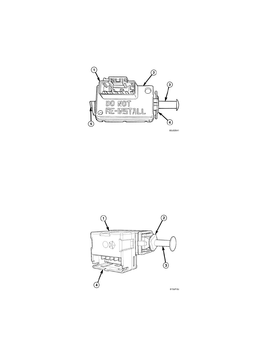
EARLY PRODUCTION
This brake lamp switch (2) is a three circuit, spring-loaded plunger actuated switch that is secured to the brake pedal support bracket on the dash panel
under the instrument panel on the driver side of the vehicle. The molded plastic switch housing has an integral connector receptacle (1) containing six
terminal pins and featuring a Connector Position Assurance (CPA) lock. The switch is connected to the vehicle electrical system through a dedicated take
out of the body wire harness.
The switch plunger (3) extends through a mounting collar (4) on one end of the switch housing. The plunger has a one time telescoping self-adjustment
feature that is activated after the switch is installed by moving an adjustment release lever (5) on the opposite end of the switch housing clockwise, until
it locks into a position that is horizontal and parallel to the connector receptacle.
This brake lamp switch cannot be readjusted or repaired. If the switch is damaged, ineffective, or removed from its mounting position for any reason, it
must be replaced with a new unit.
LATE PRODUCTION
This brake lamp switch (1) is a three circuit, spring-loaded plunger actuated switch that is secured to the brake pedal support bracket under the
instrument panel on the driver side of the vehicle. The molded plastic switch housing has an integral connector receptacle (4) containing six terminal
pins. The switch is connected to the vehicle electrical system through a dedicated take out of the body wire harness.
The switch plunger (3) extends through a mounting collar (2) on one end of the switch housing. The plunger has a telescoping self-adjustment feature
that is activated after the switch is installed by pulling the brake pedal upward to its normal at-rest position. The telescoping plunger can be pulled
outward from the switch housing to repeat the self-adjustment procedure if necessary.