
Journey AWD V6-3.5L (2009)
Steering Column Lock: Service and Repair
Shaft Lock Module - Removal
REMOVAL
WARNING: To avoid serious or fatal injury on vehicles equipped with airbags, disable the Supplemental Restraint System (SRS) before
attempting any steering wheel, steering column, airbag, seat belt tensioner, impact sensor, or instrument panel component
diagnosis or service. Disconnect and isolate the battery negative (ground) cable, then wait two minutes for the system capacitor to
discharge before performing further diagnosis or service. This is the only sure way to disable the SRS. Failure to take the proper
precautions could result in accidental airbag deployment.
NOTE: The shaft lock module cannot be removed from the steering column while the locking bolt is in the locked position without irreversibly
damaging the column. Before attempting service, insert a valid FOB with Integrated Key (FOBIK) into the ignition switch, then
rotate the steering wheel from side to side. If the steering wheel can be rotated, the locking bolt is in the unlocked position. Leave the
FOBIK in the ignition switch until service has been completed. If the steering wheel cannot be rotated, test and repair the wiring
circuits between the module and the ignition switch as required. If no problem is found in these circuits, the module has failed with the
locking bolt in the locked position and both the module and the steering column must be replaced with new units.
1. Insert a FOB with Integrated Key (FOBIK) into the ignition switch to move the shaft lock module locking bolt to the unlocked position. Leave the
FOBIK in the ignition switch while the shaft lock module service is being completed.
2. Disconnect and isolate the battery negative cable.
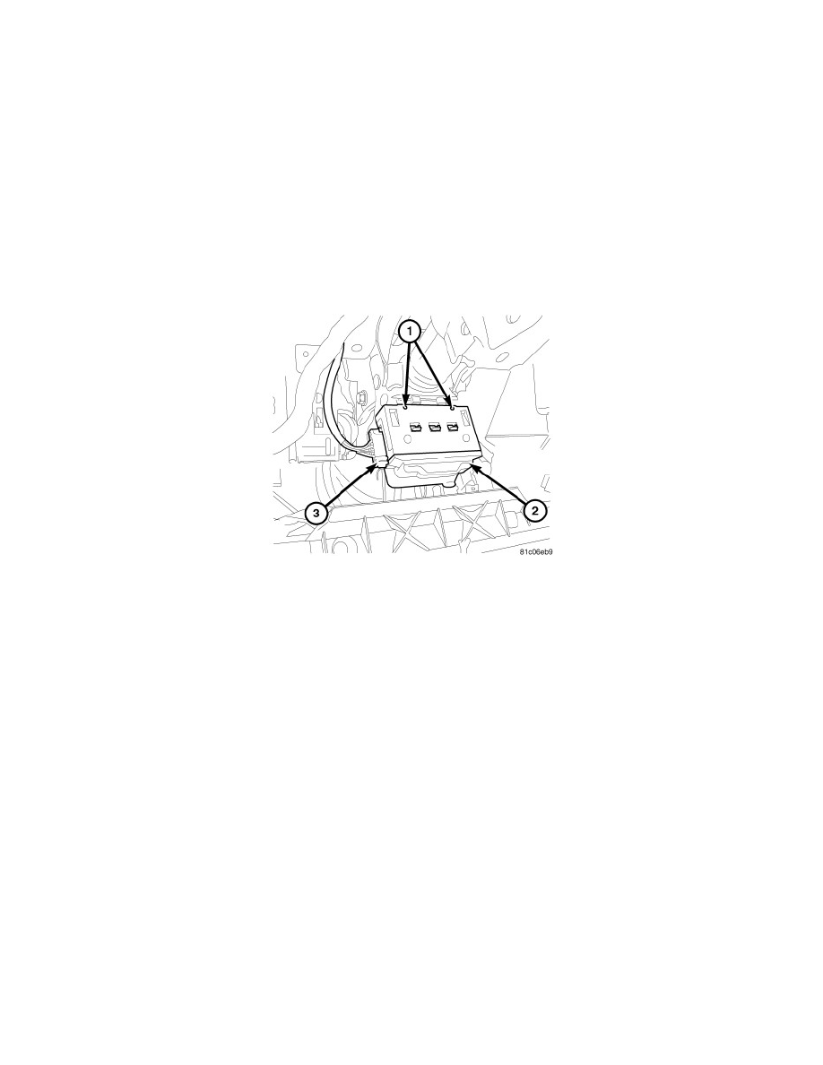
3. Disconnect the instrument panel wire harness connector (3) from the shaft lock module (2) connector receptacle.
4. Remove the steering column from the vehicle. See: Service and Repair/Removal and Replacement/Steering Column - Removal.
5. Depress the two spring clips that secure the shaft lock module to the mounting bracket on the steering column by inserting a suitable drift or punch
into the release holes (1) on the upper surface of the bracket opposite the module.
6. While holding both of the spring clips depressed, slide the module toward the base of the column far enough to disengage the engagement tabs and
slide tabs on the module from the slots and channels in the bracket.
7. Remove the module from the steering column bracket.