
Lancer Shelby L4-135 2.2L SOHC Turbo (1989)
Installing Pulley Assembly
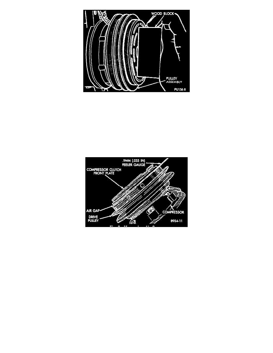
3. Install pulley assembly onto compressor. If necessary, tap gently with a block of wood on the friction surface.
CAUTION: Do not mar the pulley frictional surface.
4. Install pulley assembly retaining snap ring, bevel side outward with snap ring pliers Tool C-4574. With a screwdriver, press all the way around the
snap ring to make sure it is properly seated in the groove.
5. If the original front plate assembly and pulley assembly are to be reused, the old shims can be used. If not, place a trial stack of shims, 0.100 in.
(2.54mm) thick, on the shaft against the shoulder.
6. Install front plate assembly onto shaft making sure the key enters keyway in front plate assembly hub.
Measuring Air Gap
7. With the front plate assembly tight against the shims, measure the air gap between front plate and pulley face with feeler gauges. The air gap
should be between 0.020 and 0.035 inch (.05 and O.9mm). If proper air gap is not obtained, add or subtract shims until desired air gap is
obtained.
8. Install lockwasher and shaft nut. Tighten to 155 ± 20 in. lbs. (17.5 ± 2 Nm) using torque wrench and spanner wrench tool C4563.
CAUTION: Shims may compress after tightening shaft nut Check air gap in four or more places to verify if air gap is still correct. Spin pulley for
final check.
Variable Displacement Compressor
REMOVAL AND INSTALLATION
1. Remove necessary components to gain access to the front of the compressor.