
Magnum V6-2.7L VIN R (2005)
Camshaft: Description and Operation
CAMSHAFT(S)
DESCRIPTION
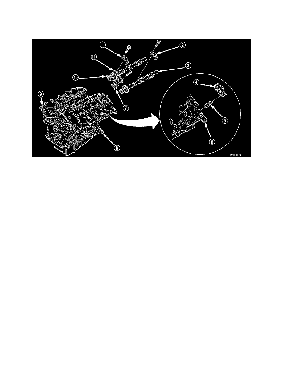
The assembled fabricated camshafts are composed of five bearing journals machined onto a hollow steel tube. The camshafts are secured in the
cylinder head (6) by the camshaft bearing caps (1&2). Six steel lobes, a secondary timing drive sprocket, and a primary sprocket/thrust flange are
pressed onto the camshaft tube using a unique assembly process. Camshaft end play is controlled by the primary camshaft sprocket attachment flange
on the intake camshafts (7) and by a thrust flange on the exhaust camshafts (3).The intake camshafts are driven by the primary chain. The exhaust
camshafts (3) are driven by the intake camshafts (10) through a secondary chain (11). The secondary chain tensioner (7) keeps tension on the
secondary chain (11).
OPERATION
The camshaft has precisely machined (egg shaped) lobes to provide accurate valve timing and duration. The camshaft is driven by the crankshaft via
drive sprockets and chains.