
Magnum V8-5.7L VIN 2 (2007)
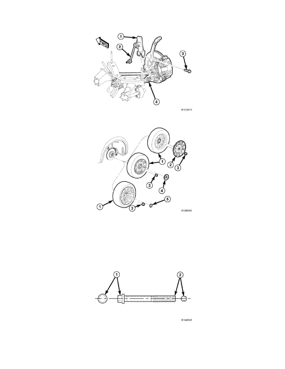
4. Install wheel speed sensor head (4) into knuckle and install mounting screw (3). Tighten screw to 11 Nm (95 in. lbs.).
5. Attach wheel speed sensor cable and routing clip (2) to brake flex hose routing bracket (5).
6. Install lower shock mounting bolt (3) attaching shock assembly (1) to lower control arm (4). Do not tighten bolt at this time.
7. Install tire and wheel assembly (1). Tighten wheel mounting nuts (3) to 150 Nm (110 ft. lbs.) (Police - 190 Nm (140 ft. lbs.)).
8. Lower vehicle.
CAUTION: Because stabilizer bar is disconnected at cradle it is important to use extra care while moving vehicle to alignment
rack/drive-on lift.
9. Position vehicle on an alignment rack/drive-on lift.
10. Tighten lower shock mounting bolt (3) to 174 Nm (128 ft. lbs.).
11. Perform wheel alignment.
CAUTION: If the control arm engine cradle bolt is a wheel alignment adjustment bolt (lengthwise grooved shaft (2)), be sure to only
tighten the nut. Do not rotate the bolt head (1) or damage to the bushing will occur.