
Mini Ram Van L4-134 2.2L SOHC VIN C 2-BBL (1987)
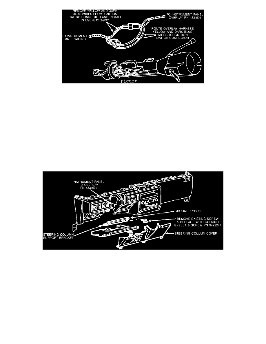
FIGURE 2-C - INSTRUMENT PANEL WIRING
3.
Disconnect the 5-way ignition switch connector and remove the yellow wire (Figure 2-C, steering column may need to be lowered to gain
access). Install the yellow wire just removed into the top half of the natural colored 2-way female connector supplied with the instrument
panel overlay harness, PN 4331574.
NOTE:
YELLOW WIRE IN FEMALE CONNECTOR MUST LINE UP WITH YELLOW WIRE IN MALE CONNECTOR
OF OVERLAY HARNESS, PN 4331574 (FIGURES 2-C AND 7).
Install the bare terminal yellow wire of the instrument panel overlay harness, PN 4331574, into the previously vacated cavity in the ignition switch
connector (Figures 2-C and 7).
4.
Remove the dark blue wire from the 5-way ignition switch connector and install into the bottom half of the natural colored 2-way female connector
of overlay harness (opposite the dark blue wire in male half of overlay harness, PN 4331574). Install the bare terminal dark blue wire from overlay
harness into previously vacated cavity in ignition switch connector (Figures 2-C and 7).
5.
Reconnect the natural colored 2-way connectors supplied with the instrument panel overlay harness and reconnect the ignition switch connector.
FIGURE 2-A
6.
Remove the far right-hand screw from the lower reinforcement steering column support bracket. Secure bare eyelet ground terminal (black wire)
from the instrument panel overlay harness, PN 4331574, to the steering column support bracket using screw, PN 9422247 (Figure 2-A). Tighten
securely.