
Monaco V6-182 3.0L SOHC (1990)
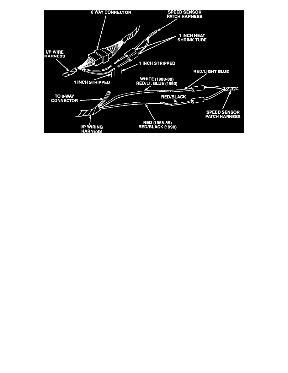
FIGURE 5
13.
Solder the red/light blue wire from the speed sensor patch harness to the white wire (red/light blue on 1990 vehicles) from the instrument panel
wire harness (Figure 5). USE ROSIN CORE SOLDER
14.
Solder the red/black wire from the speed sensor patch harness to the red wire (red/black on 1990 vehicles) from the instrument panel wire harness
(Figure 5). USE ROSIN CORE SOLDER
15.
Center the heat shrink tube over each solder joint and shrink tube using an air heat gun.
16.
Tape the two wires together using electrical tape (friction tape).
17.
Connect the eight way connector between the instrument panel wire harness and the ECU wire harness.
18.
Secure the speed sensor patch harness to the ECU harness with a tie strap.
19.
Install both ECU connectors to the ECU and insure that all wire terminals and both connectors are fully engaged to the ECU.
20.
Install the ECU to the instrument panel with the three retaining nuts.
21.
Connect the battery negative terminal.
POLICY:
Reimbursable within the provisions of the warranty.
TIME ALLOWANCE
Labor Operation No.
08-70-01-90 . . . . . . . . . . . . . . . . . . . . 0.7 Hrs.
FAILURE CODE:
61 - Intermittent operation