
Neon L4-2.0L SOHC (1995)
Tachometer: Testing and Inspection
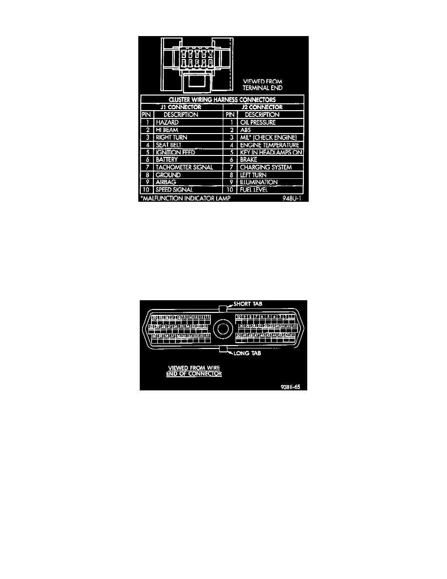
Fig. 4 Cluster Wire Harness Connector
1. Remove cluster, refer to Cluster Removal.
2. Check for battery voltage at pin 6 of the J1 of the cluster wire harness connector.
3. With the ignition switch in the ON position, check for battery voltage at pin 5 of the J1 connector.
4. Check pin 8 of the J1 connector for continuity to ground.
5. Check for tachometer signal from the power- train control module by connecting an AC DIGITAL VOLTMETER to pin 7 of the J1 connector and
ground. A reading of at least 1.0 volts should be present with the engine running.
a. If voltage is within specification, go to step 7.
b. If voltage is NOT within specification, go to step 6.
Fig. 7 Powertrain Control Module Pin Location
6. If there is less than 1.0 volts at pin 7 of the J1 connector, check for continuity between pin 7 and pin 37 of the powertrain control module
connector. Also, check the connector at the powertrain control module for damaged pins or terminal push outs.
7. If voltage is less than 1.0 volts at pin 7 of the J1 connector and there is continuity between pin 7 and pin 37 of the powertrain control module
connector, replace the powertrain control module.
8. If all tests performed test good replace the dial and gauge assembly
9. If the tachometer continues to be inoperative, replace the print circuit board.