
RAM 1500 Truck 2WD V8-4.7L VIN N (2002)
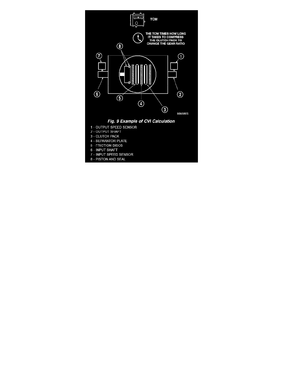
Fig. 9 Example Of CVI Calculation
By comparing the two inputs, the TCM can determine transmission gear position. This is important to the CVI calculation because the TCM
determines CVIs by monitoring how long it takes for a gear change to occur (Fig. 9).
Gear ratios can be determined by using the DRB III Scan Tool and reading the Input/Output Speed Sensor values in the "Monitors" display Gear
ratio can be obtained by dividing the Input Speed Sensor value by the Output Speed Sensor value.
For example, if the input shaft is rotating at 1000 rpm and the output shaft is rotating at 500 rpm, then the TCM can determine that the gear ratio is
2:1. In direct drive (3rd gear), the gear ratio changes to 1:1. The gear ratio changes as clutches are applied and released. By monitoring the length
of time it takes for the gear ratio to change following a shift request, the TCM can determine the volume of fluid used to apply or release a friction
element.
The volume of transmission fluid needed to apply the friction elements are continuously updated for adaptive controls. As friction material wears,
the volume of fluid need to apply the element increases.
Certain mechanical problems within the input clutch assembly can cause inadequate or out-of-range element volumes. Also, defective Input/Output
Speed Sensors and wiring can cause these conditions. The following chart identifies the appropriate clutch volumes and when they are
monitored/updated: