
RAM 1500 Truck 4WD V8-5.9L VIN Z (2002)
Compressor Clutch: Description and Operation
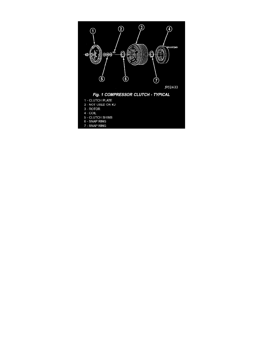
Fig. 1 Compressor Clutch - Typical
The compressor clutch assembly consists of a stationary electromagnetic coil, a rotor bearing and rotor assembly and a clutch plate. The electromagnetic
coil unit and the rotor bearing and rotor assembly are each retained on the nose of the compressor front housing with snap rings. The clutch plate is
keyed to the compressor shaft and secured with a nut. These components provide the means to engage and disengage the compressor from the engine
serpentine accessory drive belt.
When the clutch coil is energized, it magnetically draws the clutch into contact with the rotor and drives the compressor shaft. When the coil is not
energized, the rotor freewheels on the clutch rotor bearing, which is part of the rotor. The compressor clutch and coil are the only serviced parts on the
compressor.
The compressor clutch engagement is controlled by several components: the A/C Heater mode control switch, the A/C high pressure transducer, the
compressor clutch relay, and the (JTEC). The JTEC may delay compressor clutch engagement for up to thirty seconds. Refer to Electronic Control
Modules for more information on the JTEC controls.