
RAM 1500 Truck 4WD V8-5.9L VIN Z (2002)
Fog/Driving Lamp Relay: Description and Operation
FOG LAMP RELAY
If equipped, the fog lamp switch is a direct input to the instrument cluster. The instrument cluster sends a PCI bus request to the FCM to turn ON the
fog lamp relay.
The fog lamp relay is then actuated by the FCM through low side control. This circuit is electronically controlled and continuously monitored for
malfunctions. The FCM "learns" that the vehicle is equipped with fog lamps by reading the instrument cluster PCI bus message.
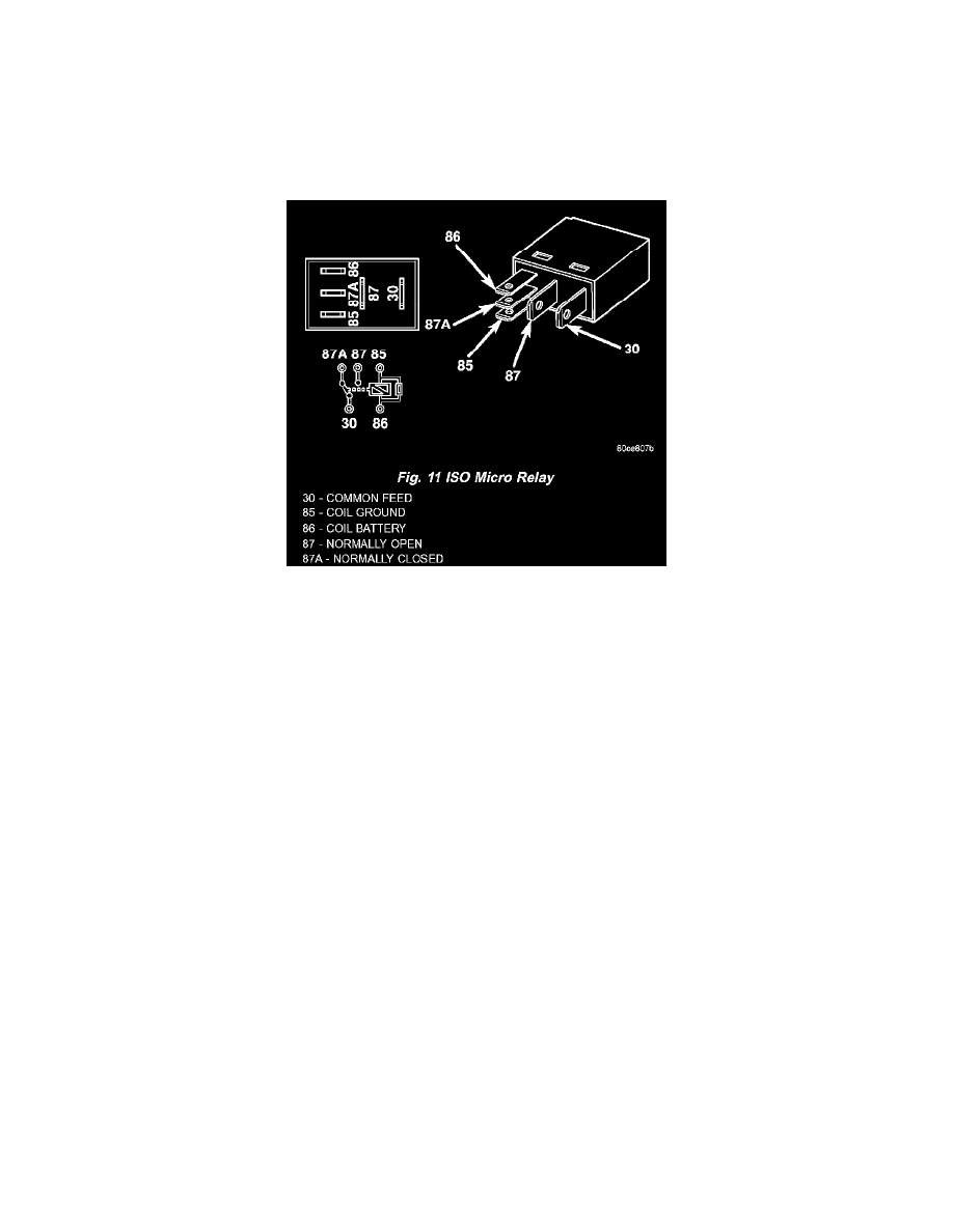
Fig.11 ISO Micro Relay
The front fog lamp relay is located in the Power Distribution Center (PDC) See: Maintenance/Fuses and Circuit Breakers/Relay Box Applications and
ID in the engine compartment of the vehicle. The front fog lamp relay is a conventional International Standards Organization (ISO) micro relay.
Relays conforming to the ISO specifications have common physical dimensions, current capacities, terminal patterns, and terminal functions. The
relay is contained within a small, rectangular, molded plastic housing and is connected to all of the required inputs and outputs by five integral male
spade-type terminals that extend from the bottom of the relay base.
The front fog lamp relay cannot be adjusted or repaired and, if faulty or damaged, the unit must be replaced.
The front fog lamp relay is an electromechanical switch that uses a low current input from the Front Control Module (FCM) to control a high current
output to the front fog lamps. The movable common feed contact point is held against the fixed normally closed contact point by spring pressure.
When the relay coil is energized, an electromagnetic field is produced by the coil windings. This electromagnetic field draws the movable relay
contact point away from the fixed normally closed contact point, and holds it against the fixed normally open contact point. When the relay coil is
de-energized, spring pressure returns the movable contact point back against the fixed normally closed contact point. A resistor is connected in parallel
with the relay coil in the relay, and helps to dissipate voltage spikes and electromagnetic interference that can be generated as the electromagnetic field
of the relay coil collapses.
The front fog lamp relay terminals are connected to the vehicle electrical system through a connector receptacle in the Power Distribution Center
(PDC). The inputs and outputs of the front fog lamp relay include:
-
Common Feed Terminal - The common feed terminal (30) receives battery voltage at all times from a fuse in the PDC through a fused B(+)
circuit.
-
Coil Ground Terminal - The coil ground terminal (85) is connected to a control output of the Front Control Module (FCM) through a front fog
lamp relay control circuit. The FCM controls front fog lamp operation by controlling a ground path through this circuit.
-
Coil Battery Terminal - The coil battery terminal (86) receives battery voltage at all times from a fuse in the PDC through a fused B(+) circuit.
-
Normally Open Terminal - The normally open terminal (87) is connected to the front fog lamps through a front fog lamp relay output circuit and
provides battery voltage to the front fog lamps whenever the relay is energized.
-
Normally Closed Terminal - The normally closed terminal (87A) is not connected in this application.
The front fog lamp relay can be diagnosed using conventional diagnostic tools and methods.