
RAM 1500 Truck 4WD V8-5.9L VIN Z (2002)
Air Bag Control Module: Description and Operation
Airbag Control Module (ACM)
WARNING:
-
THE AIRBAG SYSTEM IS A SENSITIVE, COMPLEX ELECTROMECHANICAL UNIT.
-
THE AIRBAG CONTROL MODULE CONTAINS THE IMPACT SENSOR, WHICH ENABLES THE SYSTEM TO DEPLOY THE
AIRBAG.
-
BEFORE ATTEMPTING TO DIAGNOSE OR SERVICE ANY AIRBAG SYSTEM OR RELATED STEERING WHEEL, STEERING
COLUMN, OR INSTRUMENT PANEL COMPONENTS YOU MUST FIRST DISCONNECT AND ISOLATE THE BATTERY
NEGATIVE (GROUND) CABLE. THEN WAIT TWO MINUTES FOR THE SYSTEM CAPACITOR TO DISCHARGE BEFORE
FURTHER SYSTEM SERVICE.
-
THIS IS THE ONLY SURE WAY TO DISABLE THE AIRBAG SYSTEM. FAILURE TO DO THIS COULD RESULT IN
ACCIDENTAL AIRBAG DEPLOYMENT AND POSSIBLE PERSONAL INJURY.
-
NEVER STRIKE OR KICK THE AIRBAG CONTROL MODULE, AS IT CAN DAMAGE THE IMPACT SENSOR OR AFFECT ITS
CALIBRATION. IF AN AIRBAG CONTROL MODULE IS ACCIDENTALLY DROPPED DURING SERVICE, THE MODULE MUST
BE SCRAPPED AND REPLACED WITH A NEW UNIT
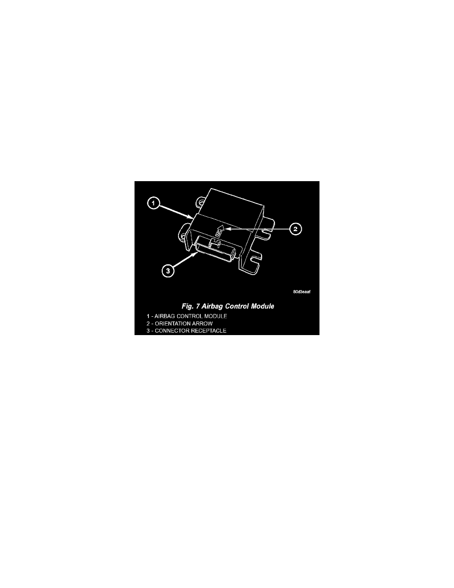
Fig. 7 Airbag Control Module
AIRBAG CONTROL MODULE
The Airbag Control Module (ACM) is secured with four screws to the top mounting surface of a stamped steel bracket welded onto the top of the
floor panel transmission tunnel forward of the instrument panel center support bracket and below the instrument panel center stack in the passenger
compartment of the vehicle. Concealed within a hollow in the center of the die cast aluminum ACM housing is the electronic circuitry of the ACM
which includes a microprocessor, an electronic impact sensor, an electromechanical safing sensor, and an energy storage capacitor. A stamped
metal cover plate is secured to the bottom of the ACM housing with four screws to enclose and protect the internal electronic circuitry and
components.
The ACM housing has integral mounting flanges on each side. Two of the mounting flanges, one on each side, have an integral locating pin on
their lower surface. The left flanges have round mounting holes, while the flanges on the right side have slotted mounting holes. An arrow cast into
the top of the ACM housing near the rear provides a visual verification of the proper orientation of the unit, and should always be pointed toward
the front of the vehicle. A molded plastic electrical connector receptacle containing twenty-three terminal pins exits the rearward facing side of the
ACM housing. These terminal pins connect the ACM to the vehicle electrical system through a dedicated take out and connector of the instrument
panel wire harness.
The impact sensor and safing sensor internal to the ACM are calibrated for the specific vehicle, and are only serviced as a unit with the ACM. The
ACM cannot be repaired or adjusted and, if damaged or faulty it must be replaced.
The microprocessor in the Airbag Control Module (ACM) contains the front supplemental restraint system logic circuits and controls all of the
front supplemental restraint system components. The ACM uses On-Board Diagnostics (OBD) and can communicate with other electronic
modules in the vehicle as well as with the DRB III scan tool using the Programmable Communications Interface (PCI) data bus network. This
method of communication is used for control of the airbag indicator in the ElectroMechanical Instrument Cluster (EMIC) and for supplemental
restraint system diagnosis and testing through the 16-way data link connector located on the driver side lower edge of the instrument panel. (Refer
to INSTRUMENT CLUSTER/AIRBAG INDICATOR - OPERATION).