
RAM 1500 Truck 4WD V8-5.9L VIN Z (2002)
Power Door Lock Switch: Testing and Inspection
The Light-Emitting Diode (LED) illumination lamp of the power lock switch receives battery current through a fuse in the Integrated Power Module
(IPM) on a fused ignition switch output (run) circuit. The power lock switch on the driver side front door trim panel is integral to the driver door
module. (Refer to POWER LOCKS/DOOR MODULE - DIAGNOSIS AND TESTING). If the power lock switch operates, but the LED is inoperative,
check for battery current at the switch with the ignition switch in the On position. If OK, replace the faulty switch. Refer to the appropriate wiring
information. The wiring information includes wiring diagrams, proper wire and connector repair procedures, details of wire harness routing and
retention, connector pin- out information and location views for the various wire harness connectors, splices and grounds.
1. Disconnect and isolate the battery negative cable. Remove the power lock switch from the door trim panel. Disconnect the door wire harness
connector for the power lock switch from the switch connector receptacle.
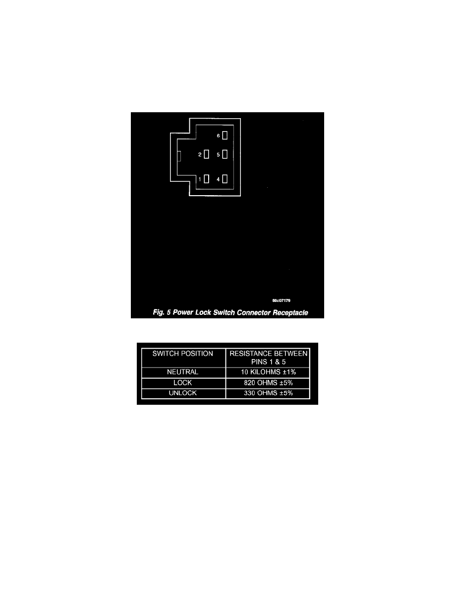
Fig.5 Powr Lock Switch Connector Receptable
Power Lock Switch Test Table
2. Test the power lock switch resistance. See the Power Lock Switch Test chart to determine if the resistance is correct for the switch in each switch
position. If not OK, replace the faulty power lock switch as required.