
RAM 1500 Truck 4WD V8-5.9L VIN Z (2002)
Seat Heater Switch: Testing and Inspection
Driver Heated Seat Switch Test
Refer to Wiring Diagrams for the location of complete heated seat system wiring diagrams.
WARNING: DISABLE THE AIRBAG SYSTEM BEFORE ATTEMPTING ANY STEERING WHEEL, STEERING COLUMN, OR
INSTRUMENT PANEL COMPONENT DIAGNOSIS OR SERVICE. DISCONNECT AND ISOLATE THE BATTERY NEGATIVE
(GROUND) CABLE, THEN WAIT TWO MINUTES FOR THE AIRBAG SYSTEM CAPACITOR TO DISCHARGE BEFORE
PERFORMING FURTHER DIAGNOSIS OR SERVICE. THIS IS THE ONLY SURE WAY TO DISABLE THE AIRBAG SYSTEM.
FAILURE TO TAKE THE PROPER PRECAUTIONS COULD RESULT IN ACCIDENTAL AIRBAG DEPLOYMENT AND POSSIBLE
PERSONAL INJURY.
1. If the problem being diagnosed involves inoperative heated seat switch back lighting and the cluster illumination lamps operate, go to Step 2. If the
problem being diagnosed involves inoperative heated seat switch back lighting and the cluster illumination lamps are also inoperative, refer to
Instrument Cluster for the proper cluster illumination lamps diagnosis and testing procedures. If the problem being diagnosed involves inoperative
heated seat switch indicator lamps and the heated seat elements do not heat, proceed. If the problem being diagnosed involves inoperative heated
seat switch indicator lamps and the heated seat elements do heat, go to Step 6. If the problem being diagnosed involves a heated seat switch
indicator lamp that remains illuminated after the heated seat has been turned OFF, refer to Heated Seat Module in Electronic Control Modules for
the location of the proper heated seat module diagnosis and testing procedures.
2. Disconnect and isolate the battery negative cable. Remove the heated seat switch and bezel unit from the instrument panel. Disconnect the
instrument panel wire harness connector from the connector receptacle on the back of the heated seat switch to be tested. Check for continuity
between the ground circuit cavity of the instrument panel wire harness connector for the heated seat switch and a good ground. There should be
continuity. If OK, go to Step 3. If not OK, repair the open ground circuit to ground as required.
3. Reconnect the battery negative cable. Turn the park lamps ON with the headlamp switch. Rotate the panel lamps dimmer thumbwheel on the
headlamp switch upward to just before the interior lamps detent. Check for battery voltage at the fused panel lamps dimmer switch signal circuit
cavity of the instrument panel wire harness connector for the heated seat switch. If OK, replace the faulty heated seat switch. If not OK, repair the
open fused panel lamps dimmer switch signal circuit to the fuse in the Integrated Power Module as required.
4. Turn the ignition switch to the ON position. Check for battery voltage at the fused ignition switch output (run) circuit cavity of the instrument
panel wire harness connector for the heated seat switch. If OK, go to Step 5. If not OK, repair the open fused ignition switch output (run) circuit to
the Integrated Power Module fuse as required.
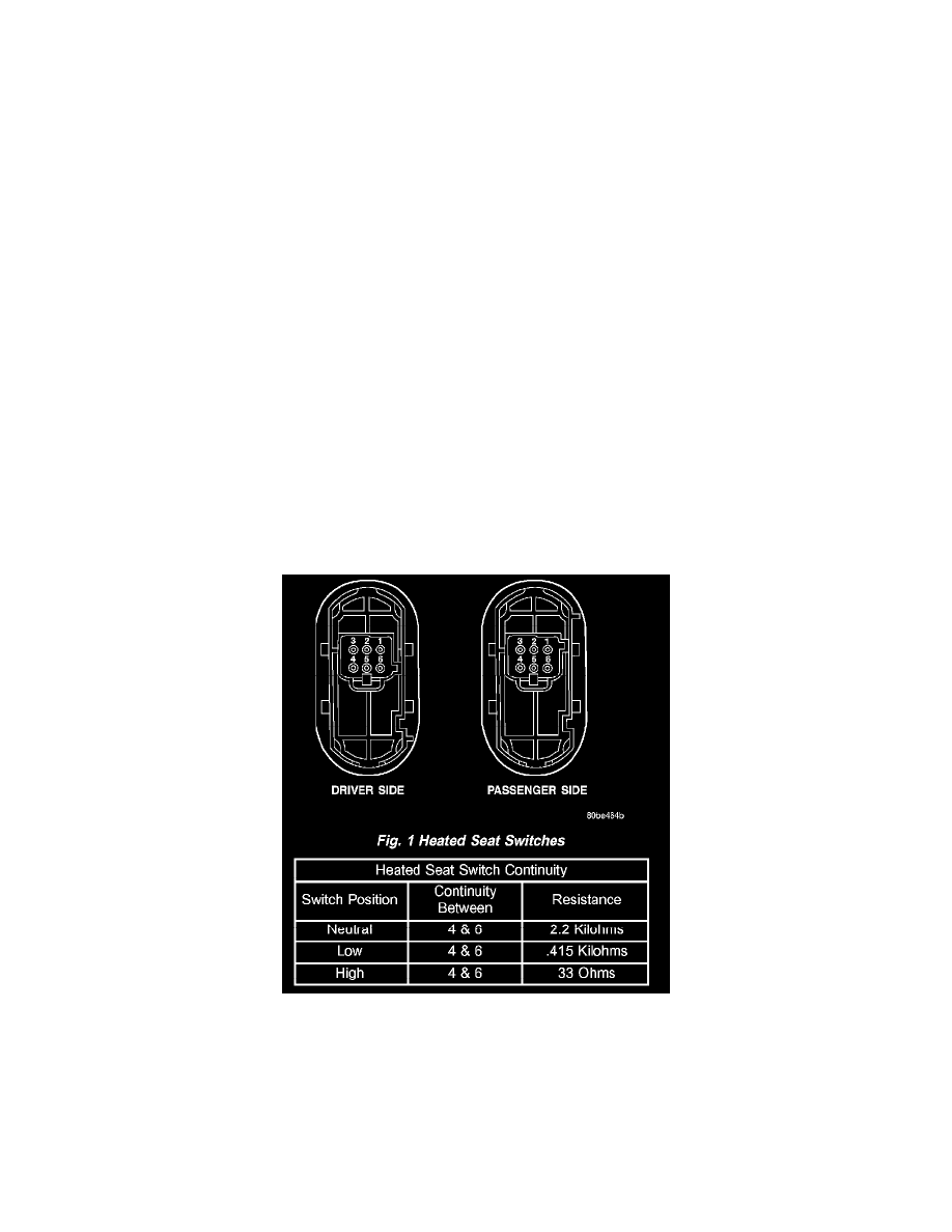
Fig. 1 Heated Seat Switches
5. Check the continuity and resistance values of the heated seat switch in the Neutral, Low and High positions as shown in the Heated Seat Switch
Continuity chart. If OK, refer to Heated Seat Module in Electronic Control Modules for the location of the proper heated seat module diagnosis
and testing procedures. If not OK, replace the faulty heated seat switch.
NOTE: ANY RESISTANCE VALUES (OHMS ) GIVEN IN THE FOLLOWING TEXT ARE SUPPLIED USING THE AUTOMATIC
RANGE GENERATED BY A FLUKE AUTOMOTIVE METER. IF ANOTHER TYPE OF MEASURING DEVICE IS USED THE VALUES
GENERATED MAY NOT BE THE SAME AS THE RESULTS SHOWN HERE, OR MAY HAVE TO BE CONVERTED TO THE RANGE
USED HERE.