
RAM 1500 Truck 4WD V8-5.9L VIN Z (2002)
MANUAL VALVE
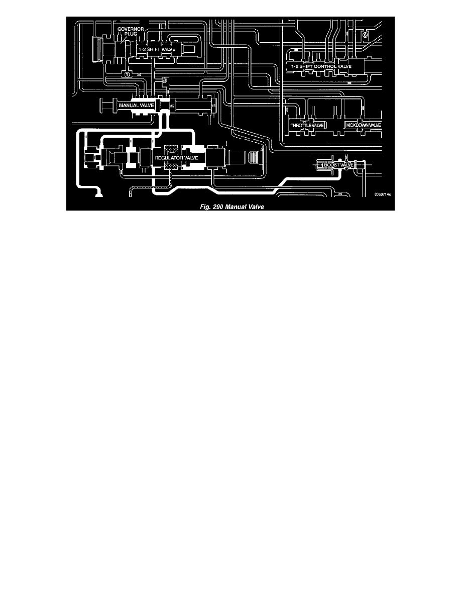
The manual valve (Fig. 290) is a relay valve. The purpose of the manual valve is to direct fluid to the correct circuit needed for a specific gear or driving
range. The manual valve, as the name implies, is manually operated by the driver with a lever located on the side of the valve body. The valve is
connected mechanically by either a cable or linkage to the gearshift mechanism. The valve is held in each of its positions by a spring-loaded roller or ball
that engages the "roostercomb" of the manual valve lever.
CONVERTER CLUTCH LOCK-UP VALVE
The Torque Converter Clutch (TCC) lock-up valve controls the back (ON) side of the torque converter clutch. When the PCM energizes the TCC
solenoid to engage the converter clutch piston, pressure is applied to the TCC lock-up valve, which moves to the right and applies pressure to the torque
converter clutch.
CONVERTER CLUTCH LOCK-UP TIMING VALVE
The Torque Converter Clutch (TCC) lock-up timing valve is there to block any 4-3 downshift until the TCC is completely unlocked and the clutch is
disengaged.
SHUTTLE VALVE
The assembly is contained in a bore in the valve body above the shift valves. When the manual valve is positioned in the Drive range, throttle pressure
acts on the throttle plug of the shuttle valve (Fig. 282) to move it against a spring, increasing the spring force on the shuttle valve. During a part or full
throttle 1-2 upshift, the throttle plug is bottomed by throttle pressure, holding the shuttle valve to the right against governor pressure, and opening a
by-pass circuit. The shuttle valve controls the quality of the kickdown shift by restricting the rate of fluid discharge from the front clutch and servo
release circuits. During a 3-2 kickdown, fluid discharges through the shuttle by-pass circuit. When the shuttle valve closes the by-pass circuit, fluid
discharge is restricted and controlled for the application of the front band. During a 2-3 "lift foot" upshift, the shuttle valve by-passes the restriction to
allow full fluid flow through the by-pass groove for a faster release of the band.