
RAM 1500 Truck 4WD V8-5.9L VIN Z (2002)
6. Remove pinion yoke companion flange bolts.
7. Slide slip yoke off of the transmission or transfer case output shaft and remove propeller shaft.
INSTALLATION
1. Slide the slip yoke onto the transmission/transfer case output shaft.
2. Align and install center bearing on crossmember, if necessary and tighten nuts to 54 Nm (40 ft. lbs.).
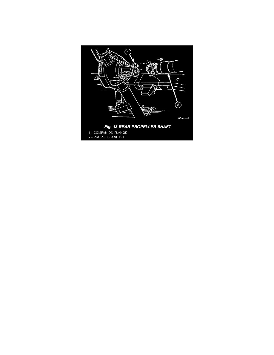
3. Align reference marks on the propeller shaft yoke and pinion companion flange (Fig. 13).
4. Tighten pinion companion flange bolts to 115 Nm (85 ft. lbs.).
5. Lower the vehicle.
Standard Procedure - Propeller Shaft Angle
Standard Procedure - Propeller Shaft Angle
This procedure applies to both the front/rear propeller shafts. To obtain the front output angle (A) on the front propeller shaft, place the inclinometer the
machined surface of the CV joint.
PROPELLER SHAFT ANGLE
1. To check driveline alignment, raise and support the vehicle at the axles as level as possible. Allow the wheels and propeller shaft to turn.
2. Remove any external bearing snap rings, if equipped from universal joint so protractor base sits flat.
3. Rotate the shaft until transmission/transfer case output yoke bearing is facing downward.
NOTE: Always make measurements from front to rear and from the same side of the vehicle.