
RAM 2500 Truck 4WD L6-5.9L DSL Turbo VIN 6 (1999)
Rotor Install
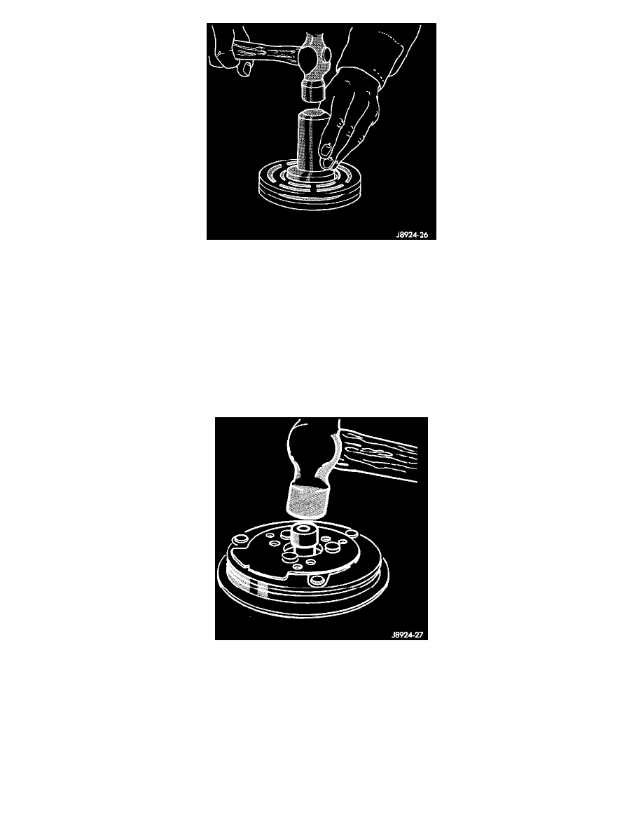
5. Place the driver tool assembly into the bearing cavity on the rotor. Make certain the outer edge of the tool rests firmly on the rotor bearing inner
race.
6. Tap the end of the driver while guiding the rotor to prevent binding. Tap until the rotor bottoms against the compressor front housing hub. Listen
for a distinct change of sound during the tapping process, to indicate the bottoming of the rotor.
7. Install the external front rotor snap ring with snap ring pliers. The bevel side of the snap ring must be facing outward. Press the snap ring to make
sure it is properly seated in the groove.
CAUTION: If the snap ring is not fully seated in the groove it will vibrate out, resulting in a clutch failure and severe damage to the front housing
of the compressor.
8. Install the original clutch shims on the compressor shaft.
Clutch Plate Install
9. Install the clutch plate. Install the shaft key. Use the shaft protector (Special Tool 6141-2 in Kit 6460) to install the clutch plate on the compressor
shaft. Tap the clutch plate over the compressor shaft until it has bottomed against the clutch shims. Listen for a distinct change of sound during the
tapping process, to indicate the bottoming of the clutch plate.
10. Replace the compressor shaft hex nut. Tighten the nut to 14.4 Nm (10.5 ft lbs).