
RAM 2500 Truck 4WD V8-5.7L VIN D (2005)
Four Wheel Drive Selector Switch: Description and Operation
SWITCH-SELECTOR
DESCRIPTION
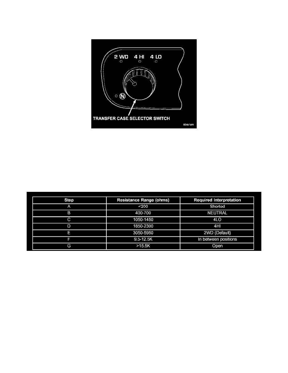
The selector switch assembly (1) is mounted in the left side of the vehicle's Instrument Panel (IP) and consists of a rotary knob connected to a resistive
network for the mode and range shift selections. Also located in this assembly is a recessed, normally open momentary switch for making shifts into
and out of transfer case NEUTRAL.A pen, or similar instrument, is used to make a NEUTRAL shift selection, thus reducing the likelihood of an
inadvertent shift request.
The selector switch also contains four light emitting diode's (LED's) to indicate the transfer case position and whether a shift is in progress.
OPERATION
As the position of the selector switch varies, the resistance between the Mode Sensor supply voltage pin and the Mode Sensor output will vary.
Hardware, software, and calibrations within the Transfer Case Control Module (TCCM) are provided that interpret the selector switch resistance as
given in the table below: SELECTOR SWITCH INTERPRETATION
SELECTOR SWITCH INTERPRETATION
For resistances between the ranges B-E shown for each valid position (T-Case NEUTRAL, 4LO, 4HI, 2WD), the TCCM may interpret the resistance
as:
^
either of the neighboring valid positions.
^
as an invalid fault position.
For resistances between the ranges E and F shown for 2WD and in-between positions, the TCCM may interpret the resistance as:
^
the 2WD position.
^
an invalid fault position.
^
a valid in-between position.
For resistances between the ranges F and G shown for in-between positions and fault condition (open), the TCCM may interpret the resistance as:
^
a valid in-between position.
^
an invalid fault position.
For resistances between the ranges A and B shown for the fault condition (short) and, T-Case NEUTRAL, the TCCM may interpret the resistance as:
^
the T-Case NEUTRAL position.
^
an invalid fault position.