
RAM 3500 Truck 2WD L6-5.9L DSL Turbo VIN 6 (1999)
Piston: Service and Repair
Removal and Installation
REMOVAL
1. Disconnect the battery cables.
2. Remove the cylinder head.
3. Remove the oil pan and suction tube.
4. Using Miller Tool 7471-B crankshaft barring tool, rotate the crankshaft so all of the pistons are below TDC.
5. Before removing the piston(s) from the bore(s):
a. Remove any carbon ridge formations or deposits at the top of the bore with a dull scraper or soft wire brush.
b. If cylinder bore wear ridges are found, use a ridge reamer to cut the ridge from the bore. DO NOT remove more metal than necessary to
remove the ridge.
NOTE: If cylinders have ridges, the cylinders are oversize and will more than likely need boring.
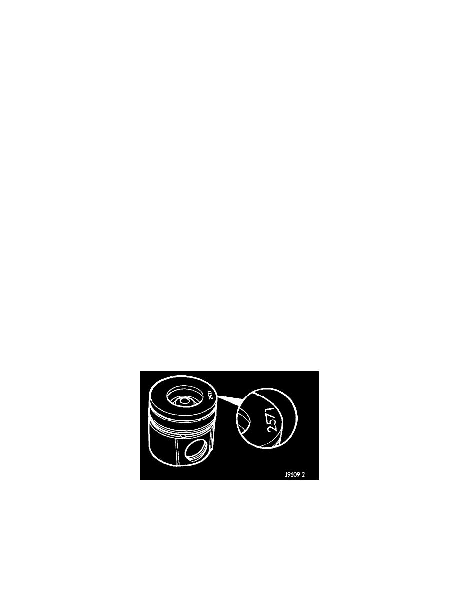
6. Using a hammer and steel stamp, identify the front of the piston by stamping the cylinder number in each piston to be removed at the top of the
piston toward the front of the engine. DO NOT stamp in the outside 5 mm (0.197 inch) of the piston diameter.
7. Mark the connecting rod and cap with the corresponding cylinder numbers.
8. Remove the connecting rod bolts and rod caps. Use care so the cylinder bores and connecting rods are not damaged.
9. Use a hammer handle or similar object to push the piston and connecting rod through the cylinder bore.
10. Store the piston/rod assemblies in a rack.
11. If a piston must be replaced, replace with the same part number (grading) that was removed.
PISTON GRADING PROCEDURE
^
When rebuilding an engine with the original cylinder block, crankshaft and pistons, make sure the pistons are installed in their original cylinder.
^
If replacing the piston(s), make sure the replacement piston(s) are the same grade as the one being replaced.
^
If a new cylinder block and/or crankshaft is used, the piston grading procedure MUST be performed to determine the proper piston grade for each
cylinder.
1. Install any of the original connecting rod and piston assemblies into the No.1 cylinder. DO NOT install the piston rings.
2. Install the upper bearing shell in the connecting rod with the tang of the bearing in the slot of the connecting rod. The connecting rod bearing shell
must be installed in the original connecting rod and cap. Use clean lubricating oil to coat the inside diameter of the connecting rod bearing shell.
3. Install the bearing shell in the connecting rod cap with the tang of the bearing in the slot to the cap. Use clean lubricating oil to coat the inside
diameter of the bearing shell.
4. The four digit number stamped on the connecting rod and cap at the parting line must match and be installed on the oil cooler side of the engine.
Install the connecting rod cap and cap screws. Tighten the cap screws to 35 Nm (26 ft. lbs.) torque.
5. Use a fine grit stone to remove any burrs from the cylinder block head deck. Zero the dial indicator to the cylinder block head deck.
6. Move the dial indicator directly over the piston pin to eliminate any side-to-side movement.
7. Rotate the crankshaft to top dead center (TDC). Rotate the crankshaft clockwise and counterclockwise to find the highest dial indicator reading.
Record the reading.
8. Remove the piston and connecting rod assembly from the No.1 cylinder and install the assembly into the No.2 cylinder. Repeat the procedure for
every cylinder using the same piston and connecting rod assembly.
Piston Grading Number Location