
RAM 3500 Truck 4WD L6-5.9L DSL Turbo VIN C (2002)
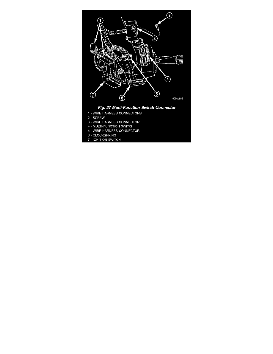
Fig. 27 Multi-Function Switch Connector
11. Gently pull the multi-function switch away from the steering column far enough to access and remove the screw that secures the instrument panel
wire harness connector for the multi-function switch to the switch connector receptacle.
12. Disconnect the instrument panel wire harness connector from the multi-function switch connector receptacle.
13. Remove the multi-function switch from the steering column.
INSTALLATION
1. Position the multi-function switch next to the steering column.
2. Reconnect the instrument panel wire harness connector for the multi-function switch to the switch connector receptacle.
3. Install and tighten the screw that secures the instrument panel wire harness connector for the multi-function switch to the switch connector
receptacle. Tighten the screw to 2 Nm (18 in. lbs.).
4. Position the multi-function switch onto the steering column.
5. Carefully lift the upper inner shroud upward far enough to access the multi-function switch mounting screws.
6. Install and tighten the two tamper proof screws (a Snap ON tamper proof Torx bit TTXR2OB2 or equivalent is required) that secure the
multi-function switch to the steering column housing. Tighten the screws to 2 Nm (18 in. lbs.).
7. Position the lower inner shroud onto the steering column. Be certain to insert the gear- shift lever hider strip into the channel located on the inside
surface of the shroud.
8. Align the locking tabs on the gearshift lever side of the upper inner shroud with the receptacles on the lower inner shroud and apply hand pressure
to snap them together.
9. From below the steering column, install and tighten the two screws that secure the lower inner shroud to the steering column housing and the upper
inner shroud. Tighten the screws to 2 Nm (18 in. lbs.).
10. Position the lower outer shroud onto the steering column.
11. From below the steering column, install and tighten the one center screw that secures the lower outer shroud to the steering column housing.
Tighten the screw to 2 Nm (18 in. lbs.).
12. Align the locking tabs on the upper outer shroud with the receptacles on the lower outer shroud and apply hand pressure to snap them together.
13. From below the steering column, install and tighten the two outboard screws that secure the lower outer shroud to the upper outer shroud. Tighten
the screws to 2 Nm (18 in. lbs.).
14. If the vehicle is so equipped, reinstall the lever into the tilt steering column adjuster on the left side of the column. Turn the lever clockwise to
screw it into the adjuster.
15. Reconnect the battery negative cable.