
RAM 3500 Chassis Cab Truck 2WD L6-6.7L DSL Turbo (2010)
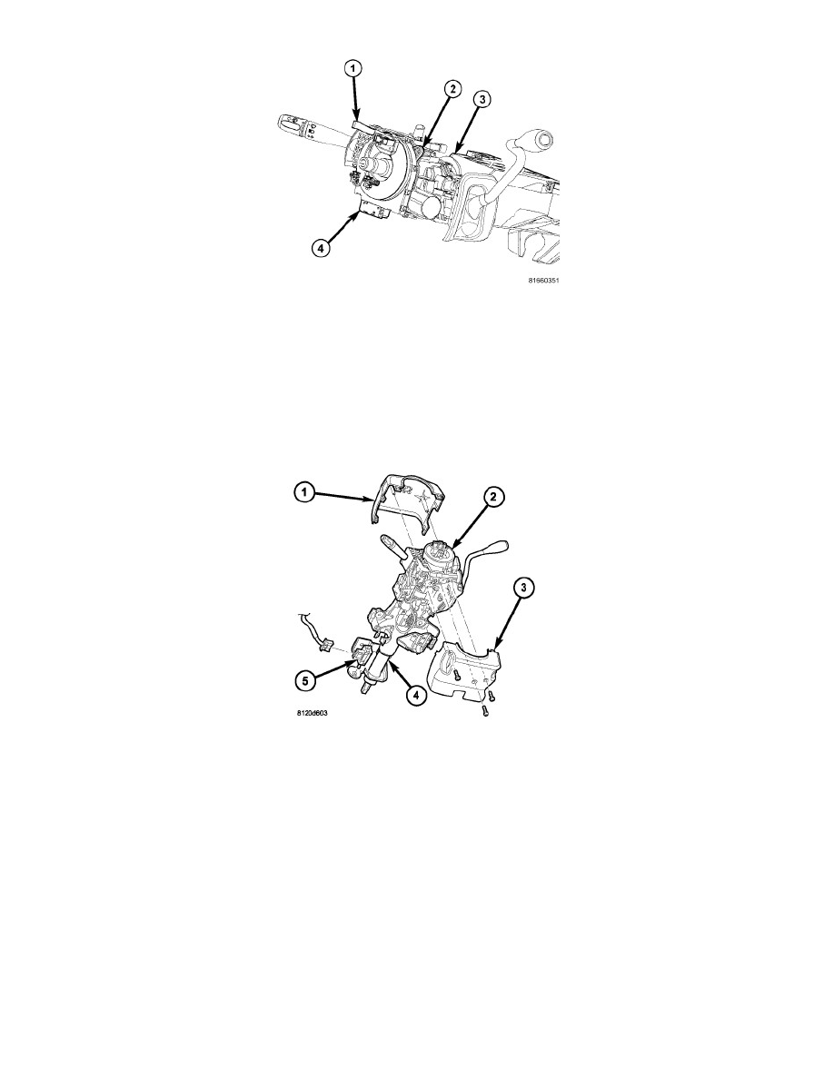
1. While holding the centered clockspring rotor and case stationary in relation to each other, or with the plastic locking pin (1) installed, carefully
slide the clockspring down over the steering column (3) upper shaft.
2. Align and seat the hole in the locating tab on the clockspring case over the locating pin on the multi-function switch mounting housing.
3. Install and tighten the two screws (2) that secure the clockspring to the multi-function switch mounting housing. Tighten the screws to 2 Nm (20
in. lbs.).
4. Reconnect the two instrument panel wire harness connectors to the two connector receptacles located below the steering column on the back of the
clockspring housing.
5. On vehicles equipped with the Electronic Stability Program (ESP), reconnect the instrument panel wire harness connector to the applied connector
for the Steering Angle Sensor (SAS) located below the steering column on the back of the clockspring housing.
6. Position the lower shroud (3) onto the steering column (4).
7. From below the steering column, install and tighten the one center screw that secures the lower shroud to the steering column. Tighten the screw to
2 Nm (20 in. lbs.).
8. Position the upper shroud (1) onto the steering column over the lower shroud. If the vehicle is equipped with an automatic transmission, be certain
to engage the gearshift lever gap hider into the opening in the right side of both shroud halves.
9. Align the snap features on the upper shroud with the receptacles on the lower shroud and apply hand pressure to snap them together.
10. Install and tighten the two outboard screws that secure the upper shroud to the lower shroud. Tighten the screws to 2 Nm (20 in. lbs.).