
Rampage L4-135 2.2L (1983)
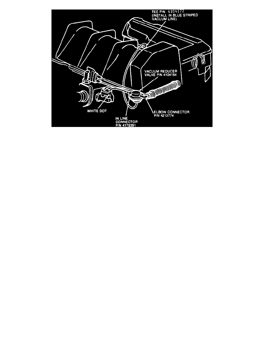
FIGURE 1
2.
Carefully cut the tape around the vacuum harness convoluted tubing at the end closest to the coolant switch (see Figure 1).
3.
Peel the convoluted tubing away from the nylon tubes and cut 2 inches from the front of the engine clip that mounts the vacuum harness to the air
pump pulley cover. Discard the cut piece of convoluted tubing.
4.
Locate the nylon vacuum tube running from the CVSCC (CCEGR) coolant switch on the side of the water control box nearest white dot on the
connector.
5.
Cut the tube located in Step 4, 2-1/2 inches from the CVSCC, and 2-1/2 inches from the vacuum harness mounting clip. When cutting the nylon
hose, use a sharp razor so the hose won't kink. Discard the unused hose (see Figure 1).
6.
Install the small end of the Inline Connector PN 4179391 on the cut end of nylon tube closest to the CVSCC. Install the small end of the Elbow
Connector PN 4213774 on the cut end of nylon tube closest to the harness mounting clip. Orient the Elbow Connector such that the 3/16 inch end
is pointed toward the CVSCC.
7.
Install the vacuum Reducer valve PN 4104184 (white nipple) between the connectors installed in step 6. Position the vacuum reducer valve such
that the third nipple points downward.
8.
Locate the blue striped vacuum hose in front of the carburetor.
9.
Cut the blue striped hose 2-1/2 inches from the air pump pulley cover, approximately in front of the air cleaner mounting bracket, and insert the
Tee PN 4104172.
10.
Cut an 18 inch length of 3/16 inch rubber hose (bulk stock PN 4105167) and install on the tee. Route this hose over the valve cover next to the air
pump pulley cover. Between the engine and the vacuum harness, loop the hose approximately 2-1/2 inches from the vacuum reducer valve and
connect to the remaining nipple.
11.
Tape the four nylon vacuum tubes together at the edge of the inline connector.
12.
Check and reset basic timing to VECI label specifications.