
Shadow Convertible L4-135 2.2L SOHC (1991)
2.
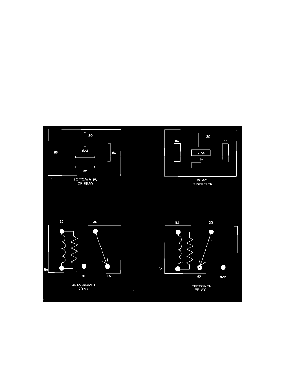
Move the voltmeter positive lead to the terminal 87 (DG/BK) wire of the ASD relay connector. Turn the ignition key to the START position and
crank the engine.
^
If no voltage is present at terminal 87 (DG/BK) wire proceed to step 3.
^
If battery voltage is present during cranking, the ASD relay is functioning normally and no further testing of the ASD relay is necessary.
3.
Move the voltmeter positive lead to the terminal 86 (DB) wire of the ASD relay connector. Turn the ignition key to the RUN position. Battery
voltage from the ignition circuit should be present.
^
If voltage is present proceed to step 4.
^
If no voltage is present there is either a bad connection or an open wire between ignition circuit J2 and terminal 86 of the ASD relay. Locate
and repair bad connector or open in wire, and test operation.
4.
Move voltmeter positive lead to terminal 85 (DB/YL) wire of the ASD relay connector. Turn ignition key to START position, and crank engine,
while observing voltage. Voltage should be present and drop to less than 1 volt within 2 seconds during cranking.
^
If voltage does not drop, proceed to step 5.
^
If voltage drops, and there is voltage at terminal 30 (RD wire) and no voltage at terminal 87 (DG/BK) the relay is bad. Replace the ASD
relay and check operation.
^
If no voltage is present, disconnect the ASD relay, and connect an ohmmeter between terminal 86 (DB wire) and terminal 85 (DB/YL wire)
of the ASD relay and check for continuity. If no continuity exists replace the ASD relay and test operation.
5.
Disconnect the 60 way Single Board Engine Controller (SBEC) connector and the ASD relay. Connect an ohmmeter between terminal 85 (DB/YL
wire) of the ASD relay connector and the DB/YL wire at pin connector no. 51 of the SBEC 60 way connector. Check for continuity.
^
If no continuity exists repair open in wire, reconnect SBEC and ASD relay, and test operation.
^
If continuity exists, the problem is computer related.
LATE MODEL VEHICLES
Relay Terminal Identification
AUTOMATIC SHUT DOWN (ASD) RELAY TERMINAL IDENTIFICATION
The following is a list of the terminal numbers, with circuit codes, and color codes, and their function:
Circuit No. Terminal No.
Color Code
Description
A14
30
RD/WT
Has battery input voltage supplied through fusible link.