
1994 Shadow Convertible Rear Window Defogger Diagram (Page 5337)
Connector Identification
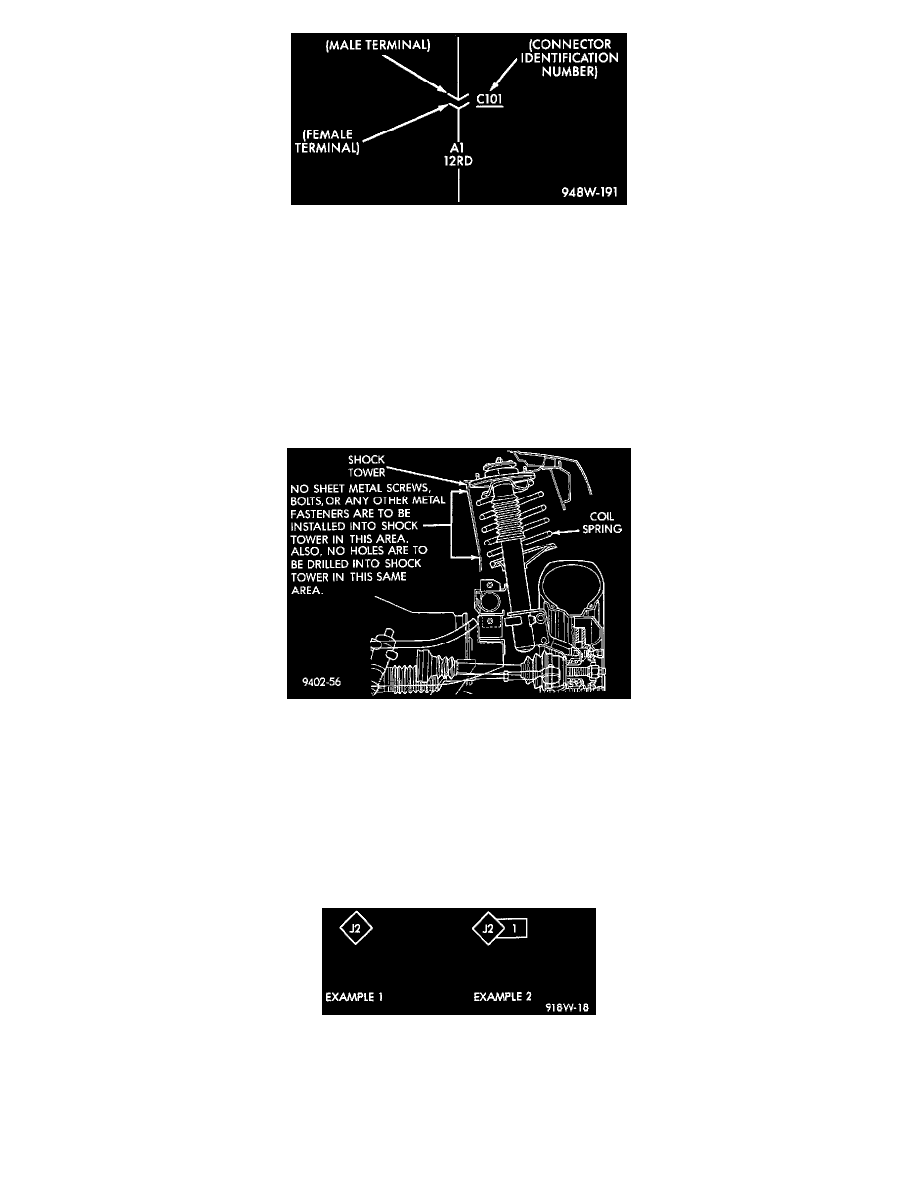
Connectors shown in the diagrams are identified using the international standard arrows for male and female terminals. A connector identifier is placed
next to the arrows to indicate the connector number.
For viewing connector pin-outs, with two or more terminals, refer to Connector Pin-Outs Index, which identifies the connector by number and provides
terminal numbering, circuit identification, wire colors, and functions.
All connectors are viewed from the terminal end unless otherwise specified. To find the connector location in the vehicle, refer to Connector Locations
Index, which uses the connector identification number from the wiring diagrams to provide a figure number reference.
Fasteners
Shock Tower To Spring Minimum Clearance Area
CAUTION: At no time when servicing a vehicle, can a sheet metal screw, bolt, or other metal fastener be installed in the strut tower to take the place of
an original plastic clip. Also, NO holes can be drilled into the front strut tower in the area shown in for the installation of any metal fasteners into the
strut tower.
Because of the minimum clearance in this area , installation of metal fasteners could damage the coil spring coating and lead to a corrosion failure of the
spring. If a plastic clip is missing, or is lost or broken during servicing of a vehicle, replace it only with the equivalent part listed in the parts catalog.
Splice Location Symbol Identification
Wiring Splice Examples
Splice locations are indicated in the diagrams by a diamond with a splice circuit code within it (example 1). If there is more than one splice per
circuit a small box will be connected to it with the splice number in it (example 2).
To locate a splice in the wiring harness determine the splice number from the diagrams then refer to Locations/Splices. This section shows the
general location of the splice in the harness.