
Sprinter 2500 V6-3.0L DSL Turbo VIN 45 (2007)
Connecting Rod: Removal and Replacement
Piston and Connecting Rod - Removal
REMOVAL
NOTE: Both the connecting rod and the connecting rod cap are paint marked to aid during assembly. Paint marks disappear after time.
If the rod and the cap are not marked with paint, paint mark or scribe them before disassembly.
1. Disconnect negative battery cable.
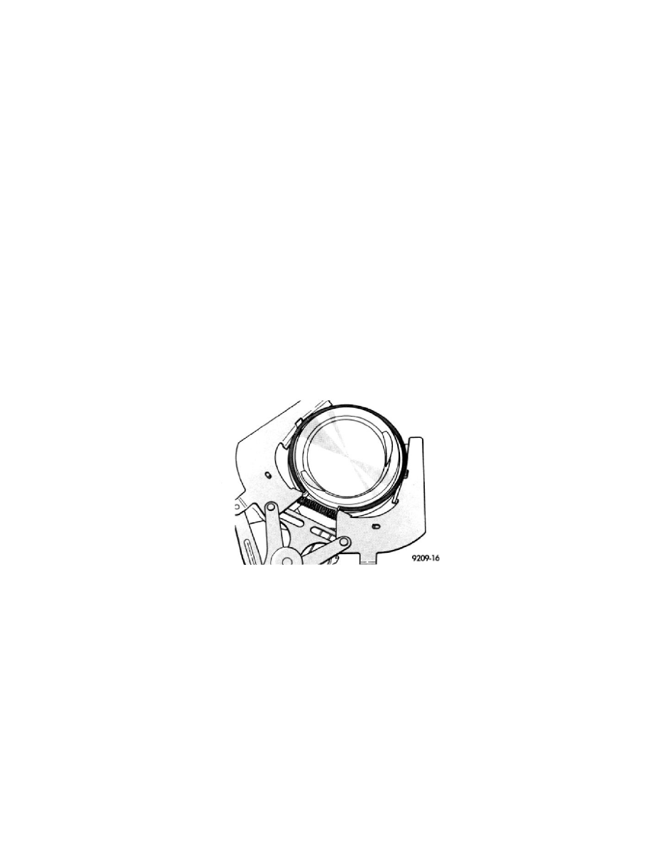
2. Remove cylinder head.
3. Raise vehicle on hoist.
4. Remove oil pan.
5. Remove oil pump pickup tube.
6. Remove top ridge of cylinder bores with a ridge reamer before removing pistons from cylinder block. Be sure to keep top of pistons covered
during this operation.
7. Piston and connecting rods must be removed from top of cylinder block. Rotate crankshaft so that each connecting rod is centered in cylinder bore.
NOTE: Be careful not to nick or scratch crankshaft journals
8. After removal, install bearing cap on the mating rod and mark pistons with matching cylinder number when removed from engine block.
PISTON PIN - REMOVAL
1. Secure connecting rods in a soft jawed vice.
2. Remove 2 snap rings securing piston pin.
3. Push piston pin out of piston and connecting rod.
PISTON RING - REMOVAL
1. ID mark on face of top and second piston rings must point toward piston crown.
2. Using a suitable ring expander, remove top and second piston rings.
3. Remove upper oil ring side rail, lower oil ring side rail and then the oil expander from piston.
4. Carefully clean carbon from piston crowns, skirts and ring grooves ensuring the 4 oil holes in the oil control ring groove are clear.
Piston and Connecting Rod - Installation
INSTALLATION
PISTON PIN INSTALLATION
1. Secure connecting rod in soft jawed vice.
2. Lubricate piston pin and piston with clean engine oil.
3. Position piston on connecting rod.
CAUTION: Ensure arrow on piston crown and the bearing cap numbers on the connecting rod are on the opposite side.
4. Install piston pin.
5. Install clips in piston to retain piston pin.