
Sprinter 2500 V6-3.0L DSL Turbo VIN 45 (2007)
NOTE: Removing and indexing the propeller shaft 180° relative to the yoke may eliminate some vibrations.
If propeller shaft is suspected of being out of balance, verify with the following procedure:
1. Place vehicle in neutral.
2. Raise and support the vehicle by the axles as level as possible.
3. Clean all foreign material from propeller shaft and universal joints.
4. Inspect propeller shaft for missing balance weights, broken welds, and bent areas.
NOTE: If propeller shaft is bent, it must be replaced.
5. Inspect universal joints for wear, properly installed and correct alignment with the shaft.
6. Check universal joint clamp screws torque.
7. Remove wheels and tires. Install wheel lug nuts to retain the brake drums/rotors.
8. Mark and number propeller shaft six inches from the pinion yoke end at four positions 90° apart.
9. Run and accelerate the vehicle until vibration occurs. Note intensity and speed the vibration occurred. Stop the engine.
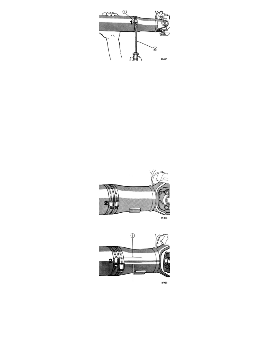
10. Install a screw clamp (1) at position 1.
11. Start engine and re-check for vibration. If little or no change in vibration is evident, move clamp to the next positions and repeat vibration test.
NOTE: If there is no difference in vibration at the other positions, the vibration may not be propeller shaft.
12. If vibration decreased, install a second clamp and repeat vibration test.
13. If additional clamp causes additional vibration, separate clamps (1) 1/2 inch above and below the mark. Repeat the vibration test.
14. Increase distance between clamps and repeat test until vibration is at the lowest level. Bend the slack end of the clamps so the screws will not
loosen.
15. If vibration remains unacceptable, preform the procedure to the front end of the propeller shaft.
16. Install the wheel and tires. Lower the vehicle.
PROPELLER SHAFT RUNOUT
1. Clean the propeller shaft surface where the dial indicator will contact the shaft.