
Sprinter 3500 V6-3.0L DSL Turbo VIN 45 (2007)
Steering Mounted Controls Communication Module: Description and Operation
Description
DESCRIPTION
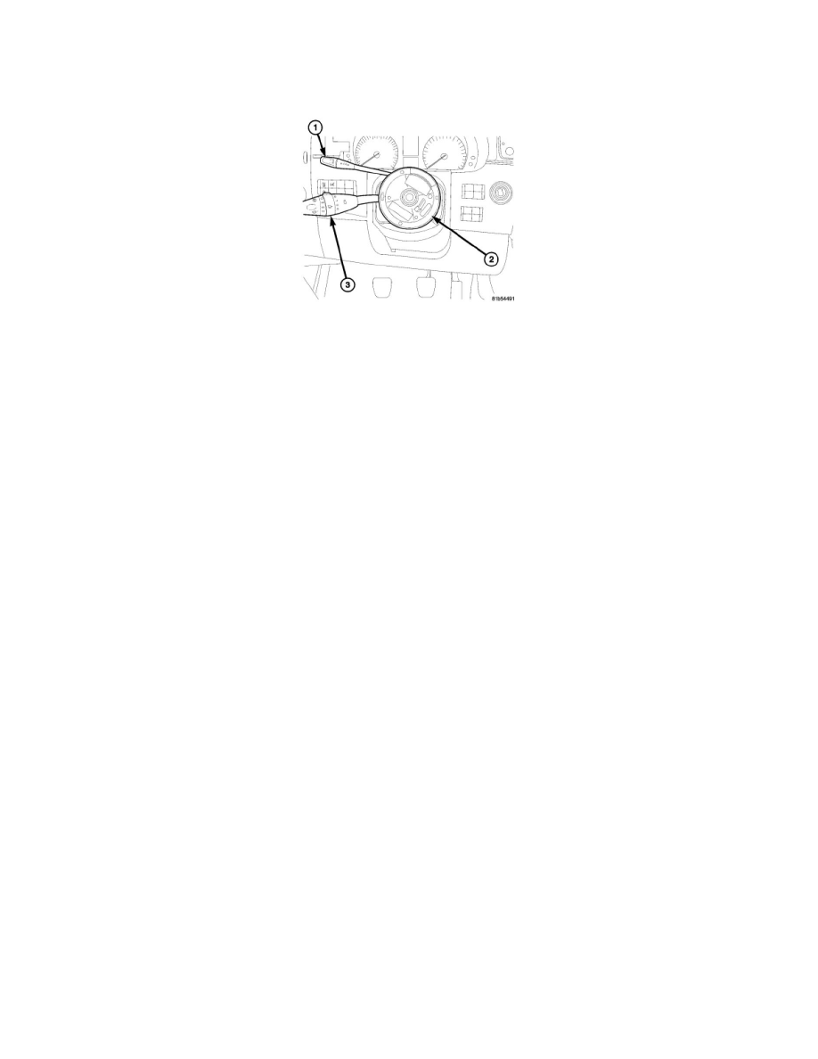
This vehicle is equipped with a Steering Control Module (SCM) (also known as the steering column module/MRM) that, along with a Steering Angle
Sensor (SAS), are internal to the housing of the clockspring (2). The clockspring is secured near the top of the steering column below the steering wheel
and is completely concealed beneath the steering column shrouds.
The microprocessor-based SCM utilizes integrated circuitry and information carried on the Controller Area Network (CAN) data bus along with several
hard wired analog and multiplexed inputs to monitor the multi-function switch, the horn switch, the optional speed control switch, the SAS and the
optional steering wheel switches. In response to those inputs, the internal circuitry and programming of the SCM allow it to control and integrate many
electronic functions and features of the vehicle through the transmission of electronic message outputs to other electronic modules in the vehicle over the
CAN data bus.
The SCM circuitry and the SAS are contained within the flat, round molded plastic clockspring case. The back (instrument panel side) of the case has a
total of three integral fixed connector receptacles. One connects the clockspring and the SCM to the vehicle electrical system through the wire harness on
the steering column, while the other two are direct interface connectors for the multi-function switch and the optional cruise control switch.
The face of the clockspring case consists of the rotating clockspring rotor with integral pigtail wires and their terminals and connector insulators. One
pigtail wire contains the driver airbag squib circuits and connects to the driver airbag, another pair of pigtail wires connects to the horn switch and the
remaining pigtail wires connect to the steering wheel jumper harness for the optional steering wheel switches. The turn signal cancel cam extends from
the back of the clockspring case but is secured to the hub of the clockspring rotor and is keyed to the steering shaft so that it rotates with the steering
wheel rotation.
A service replacement clockspring with an integral SCM and SAS is shipped with the clockspring pre-centered and with the mounting screws backed out
from the case far enough to engage the access holes in the upper surface of the rotor. The mounting screws secure the centered clockspring rotor to the
housing during shipment and handling, but allow free rotation of the rotor once the clockspring is properly installed on the steering column. There are
also clockspring centering instructions molded into the upper surface of the clockspring rotor.
The SCM cannot be adjusted or repaired. If ineffective or damaged the entire clockspring including the integral SCM and SAS must be replaced as a
unit.