
SRT-4 L4-2.4L Turbo VIN S (2004)
braking; the diagrams show only the right front wheel in an antilock braking operation.
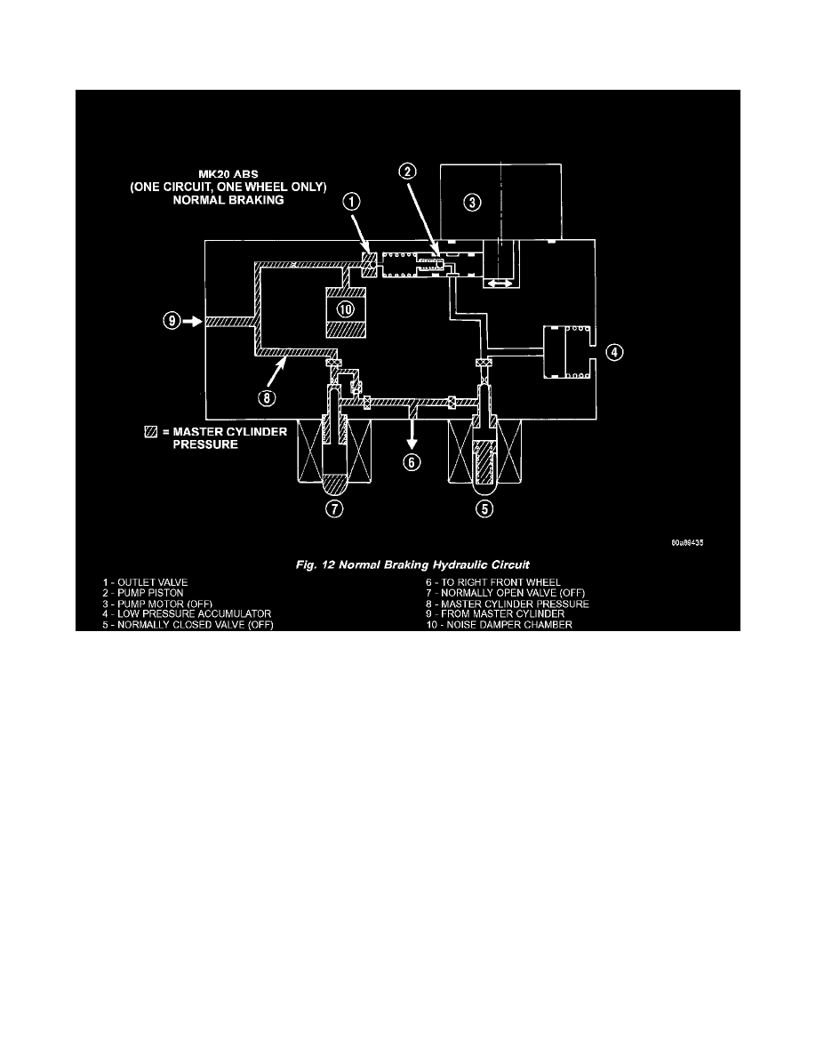
NORMAL BRAKING HYDRAULIC CIRCUIT AND SOLENOID VALVE FUNCTION
The hydraulic diagram (Fig. 12) shows the vehicle in the normal braking mode of the base brake hydraulic system. The diagram shows no wheel spin
or slip occurring relative to the speed of the vehicle. The driver is applying the brake pedal; this builds pressure in the brake hydraulic system to
engage the brakes and stop the vehicle.
ABS HYDRAULIC CIRCUIT AND SOLENOID VALVE FUNCTION