Stratus L4-2.4L DOHC (1995)

Fuel Pump Relay: Description and Operation
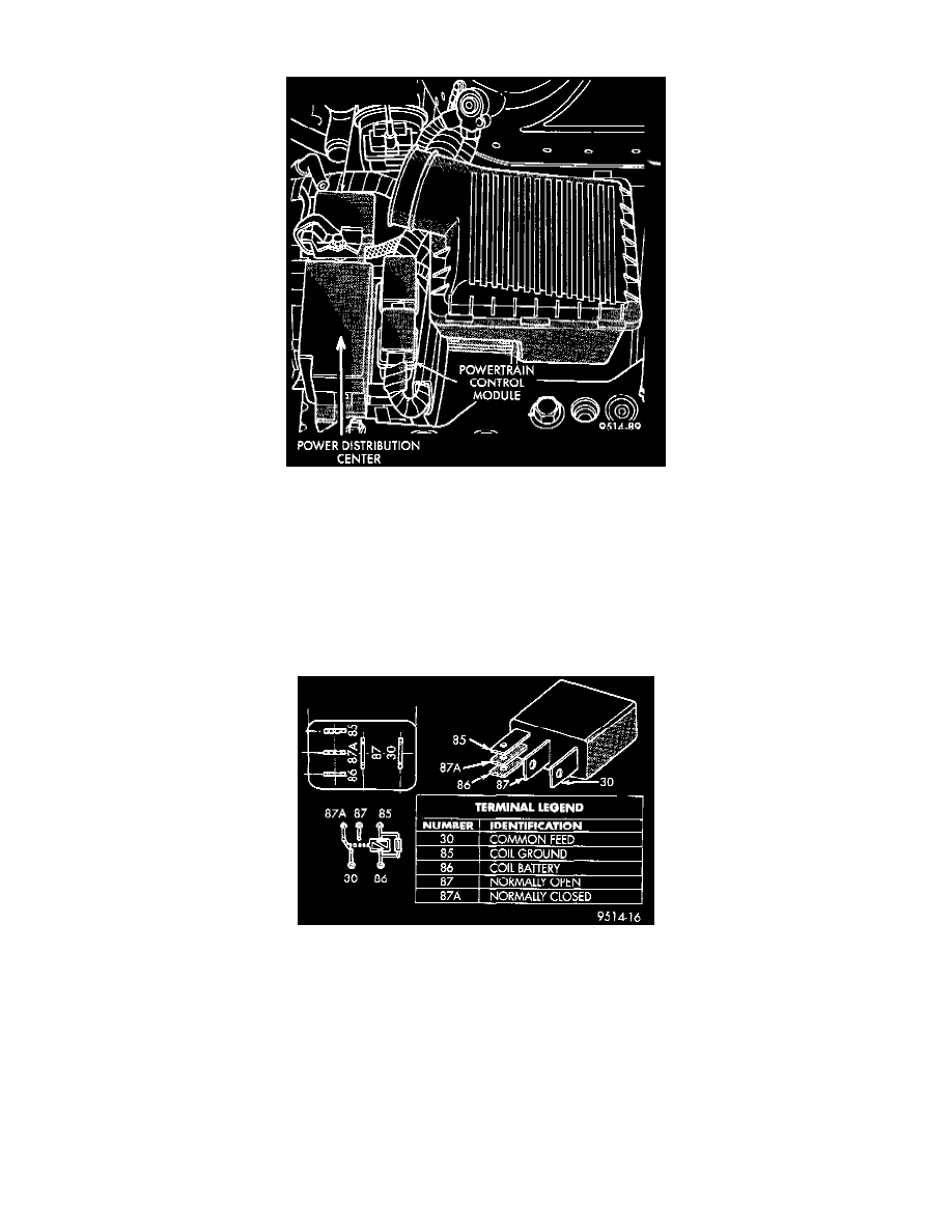
Fig. 25 Power Distribution Center (PDC)
The fuel pump relay supplies battery voltage to the fuel pump. Power for the solenoid is supplied through a 10A fuse in the Junction Block. The
contacts are supplied power through a 20A fuse in the PDC. Refer to Wiring Diagrams for circuit information.
The PCM controls the fuel pump relay by switching the ground path for the solenoid side of the relay on and off. The PCM turns the ground path
off when the ignition switch is in the Off position. When the ignition switch is in the On position, the PCM energizes the fuel pump. If the
crankshaft position sensor does not detect engine rotation, the PCM de-energizes the relay after approximately one second.
The fuel pump relay is located in the PDC Fig. 25. The inside top of the PDC cover has a label showing relay and fuse location.
Fig. 5 ASD And Fuel Pump Relay Terminals
CIRCUIT OPERATION
NOTE: The terminals on the bottom of each relay are numbered Fig. 7.
Terminal number 30 is connected to battery voltage. For both the ASD and fuel pump relays, terminal 30 is connected to battery voltage at all
times.
The PCM grounds the coil side of the relay through terminal number 85.
Terminal number 86 supplies voltage to the coil side of the relay.
When the PCM de-energizes the ASD and fuel pump relays, terminal number 87A connects to terminal 30. This is the Off position. In the off
