
Viper GTS V10-488 8.0L (1998)
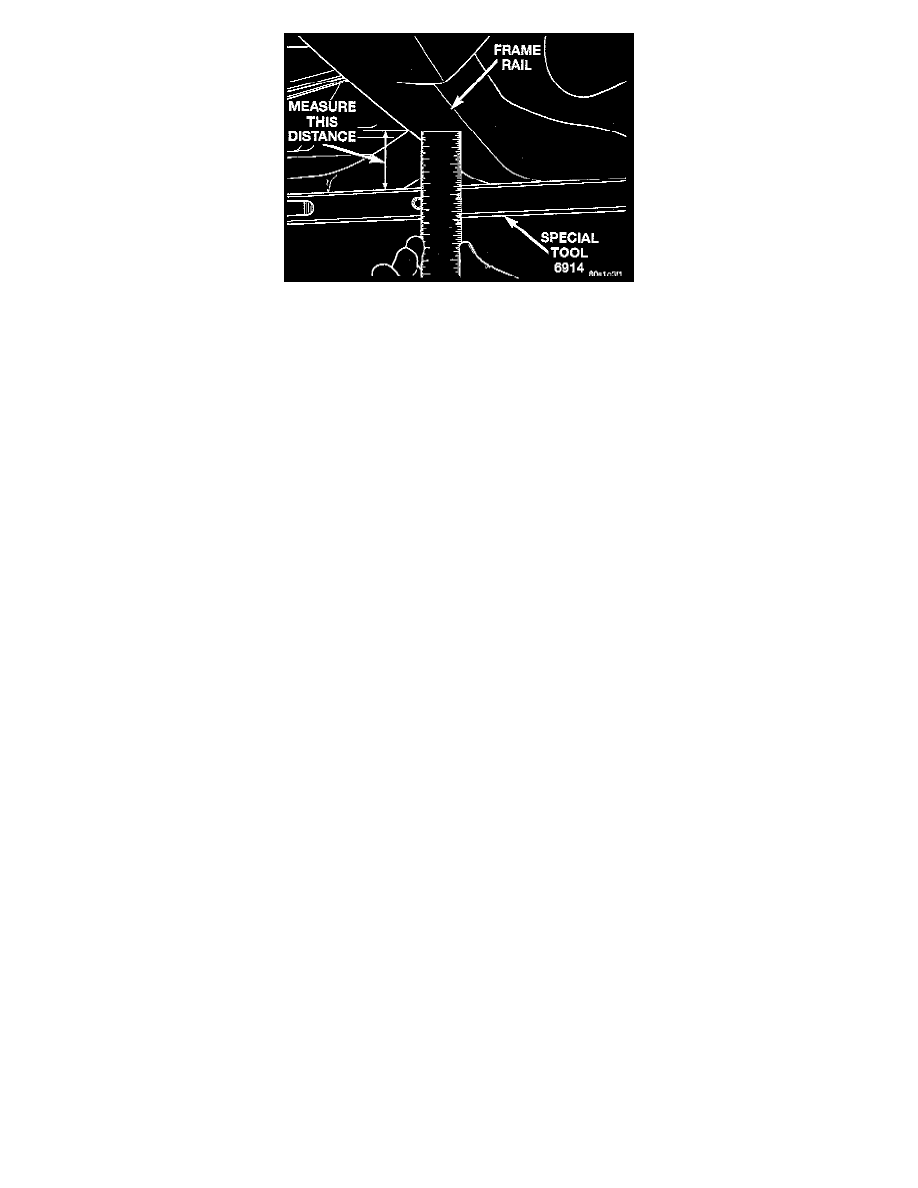
9. Check the vehicle's front design height by measuring between the Height Checking Fixture, Special Tool 6914, or equivalent and the frame rail
crossmember. Check the vehicle's rear design height by measuring between the Height Checking Fixture, Special Tool 6914, or equivalent and
both rear frame rails.
10. After ballasting the rear of the vehicle, recheck the front design height to see if the front of the vehicle lifted when rear was ballasted. If necessary
add weight to the passenger compartment of the vehicle, lowering the front of the vehicle back down to the required design height. Keep checking
front and rear of vehicle until no further adjustment is required and the vehicle is at the correct front and rear design height.
11. Tighten the mounting bolts for the following suspension components to the specified torques.
-
Front and rear lower control arm to frame bracket cam adjustment bolts and nuts to 101 Nm (75 ft. lbs.).
-
Rear upper control arm to frame bracket pivot bolts 95 Nm (70 ft. lbs.).
-
Front upper control arm to pivot bar mounting end nuts 136 Nm (100 ft. lbs.).
-
Front and rear shock absorber to frame bracket mounting bolts 136 Nm (100 ft. lbs.).
-
Front shock absorber to lower control arm mounting bolts 136 Nm (100 ft. lbs.).
-
Rear shock absorber to lower control arm mounting bolts 190 Nm (140 ft. lbs.).
12. Remove the ballast from the trunk and passenger compartment of the vehicle.
13. Lightly jounce the front and rear suspension of the vehicle to ensure vehicle is settled at curb height. When jouncing the vehicle, the vehicle must
be released at the bottom of the jounce cycle. This will ensure the vehicle's suspension will raise the vehicle to the correct curb height at the top of
the jounce cycle.
14. Check the vehicles curb height by measuring the distance from the center of the front frame rail crossmember to top surface of Vehicle Height
Checking Fixture, (at front edge).
15. Check the vehicles curb height by measuring the distance from both rear frame rails to top edge of Vehicle Height Checking Fixture.
16. If after setting the vehicle to the specified design height using the required procedure, curb height specification still is not obtained, coil spring
preload will need to be adjusted to obtain correct vehicle curb height.
17. Remove the vehicle height checking fixtures from the vehicle.